08
-
- Digital systems part 2

- ● Introduction
● Binary quantities and variables
● Logic gates
● Boolean algebra
● Combinational logic
● Boolean algebraic manipulation
● Algebraic simplification
● Karnaugh maps
● Automated methods of minimisation
● Propagation delay and hazards
● Number systems and binary arithmetic
● Numeric and alphabetic codes
● Examples of combinational logic design
-
- Karnaugh maps
- Watch the Video 📹
- ● With algebraic simplification it is not obvious whether an optimum form has been obtained
● Karnaugh maps are a graphical approach
They represent the information of a truth table within a two dimensional grid
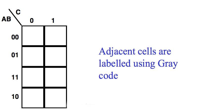
● The diagram here shows maps for systems with three and four inputs
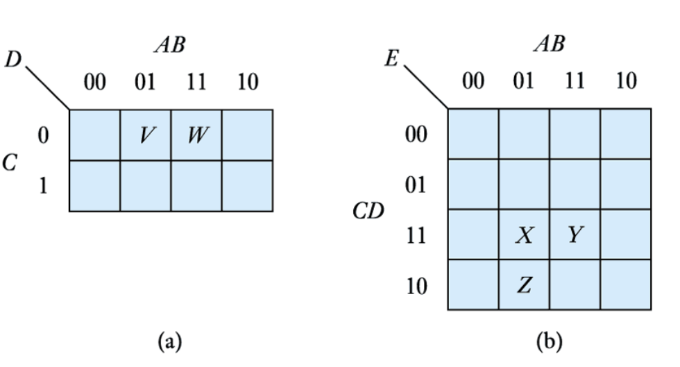
Note the numbering of the grid – Gray Code
Any adjacent cells (vertically or horizontally) differ by only one term
For example
V=\overline{A}B\overline{C}
W=AB\overline{C}
- Karnaugh Map
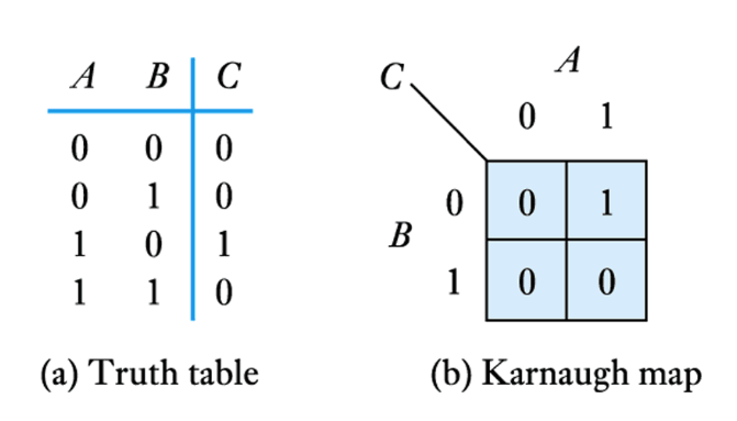
- Mapping method to give a pictorial way of simplifying digital design
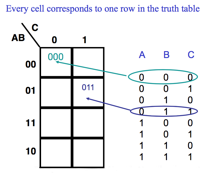
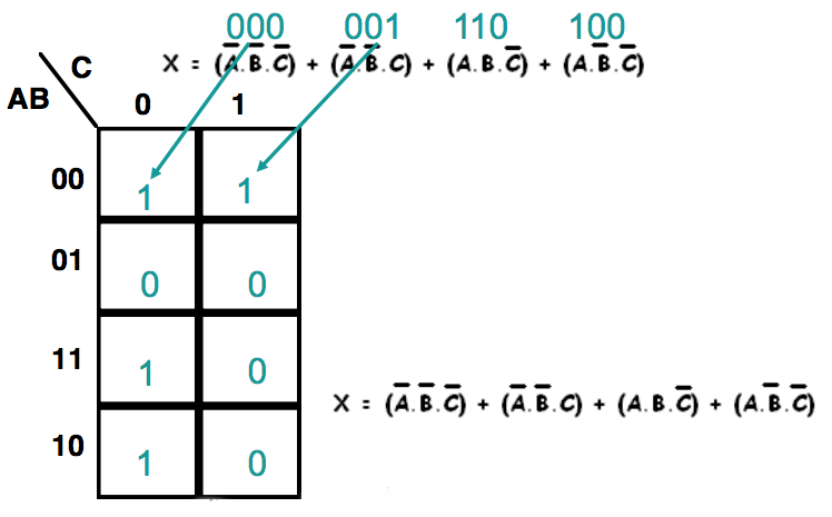
● Each minterm in the Boolean equation can be entered as a 1 in its cell
● Missing minterms are represented by a 0 in their cell
Using a three variable Karnaugh map simplify the following expression
Rules of Simplification
1. Terms can only be grouped in their binary weightings (8,4,2,1)
2.The larger the group the simpler the logic function
3.The map is an opened out sphere, therefore all edges and corners are adjacent
4.A cell may be part of more than one group
Example contd
We want to group the 1s together
Another Example
Using a three variable Karnaugh map simplify the following expression
Other Karnaugh Maps
● Consider these maps
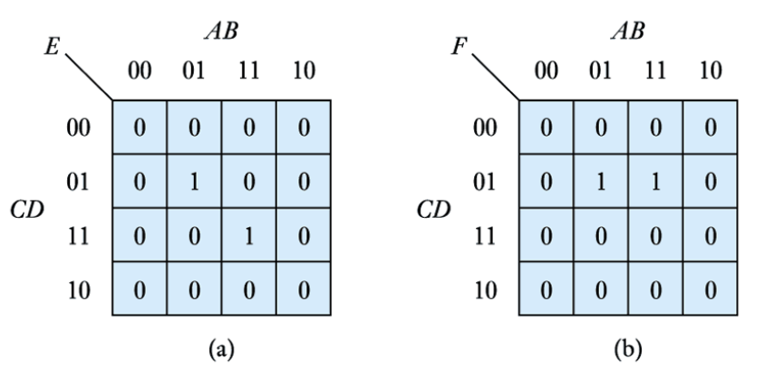
We can extract the algebraic expressions, as in a truth table
E=\overline{A}B\overline{C}D+ABCD
F=\overline{A}B\overline{C}D+AB\overline{C}D
=B\overline{C}D(A+\overline{A})
=B\overline{C}D
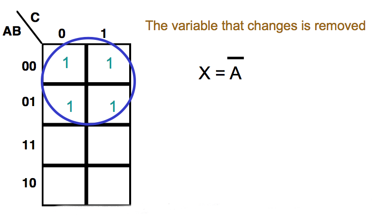
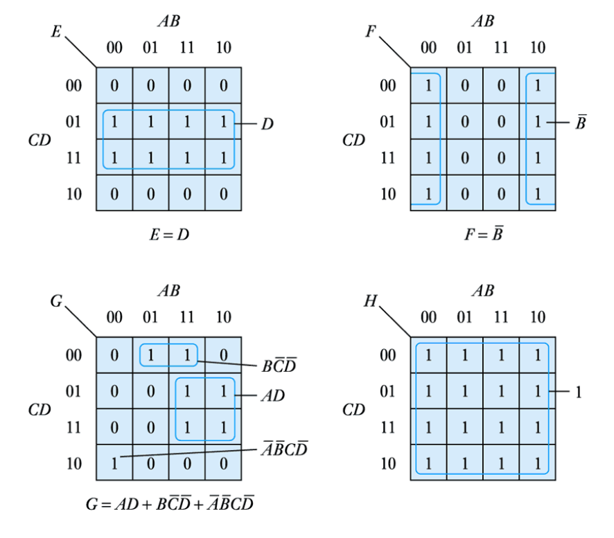
● When adjacent cells contain '1's they can always be combined, thus simplifying the expression
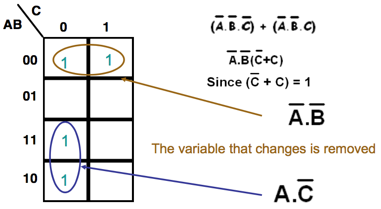
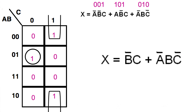
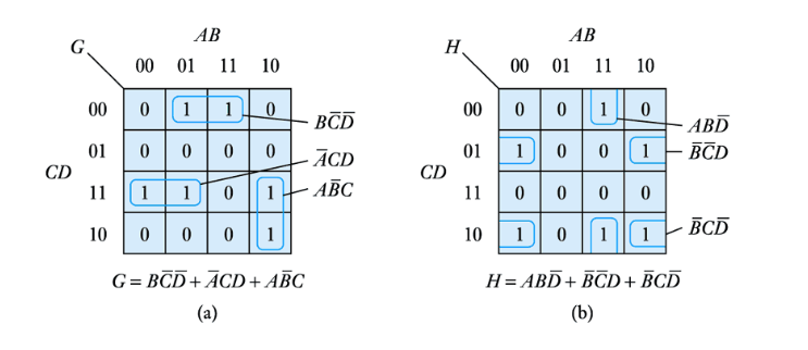
● We group terms on the map by drawing a loop around them. The expression for this group is made up of the terms that are consistent for the cells within
● The expression for the function is the sum of the groups
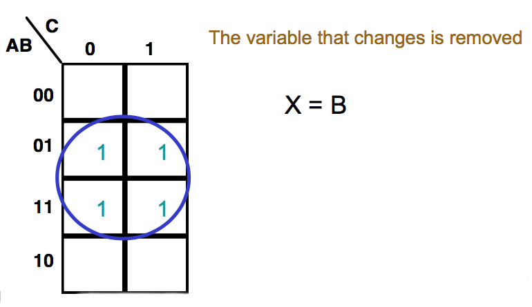
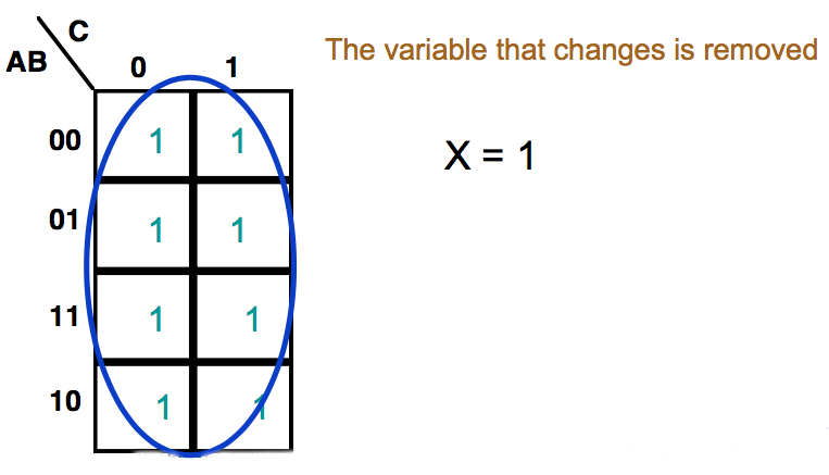
● Larger groups can also be combined provided that they follow certain rules
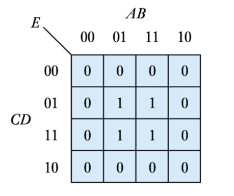
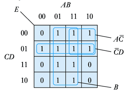
● The example here contains four cells
E=\overline{A}B\overline{C}D+AB\overline{C}D+\overline{A}BCD+ABCD
=B\overline{C}D(A+\overline{A})+BCD(A+\overline{A})
=B\overline{C}D+DCB
=BD(C+\overline{C})
=BD
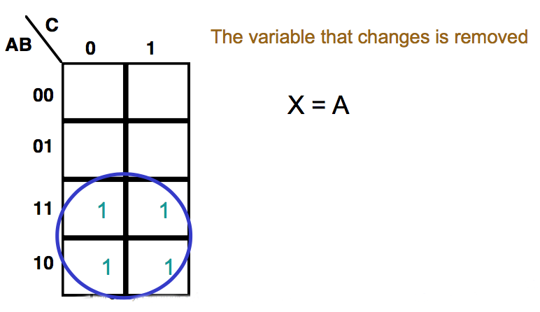
● Again, the expression for the group is made up of the terms that are consistent for the cells within
● Allowable groups
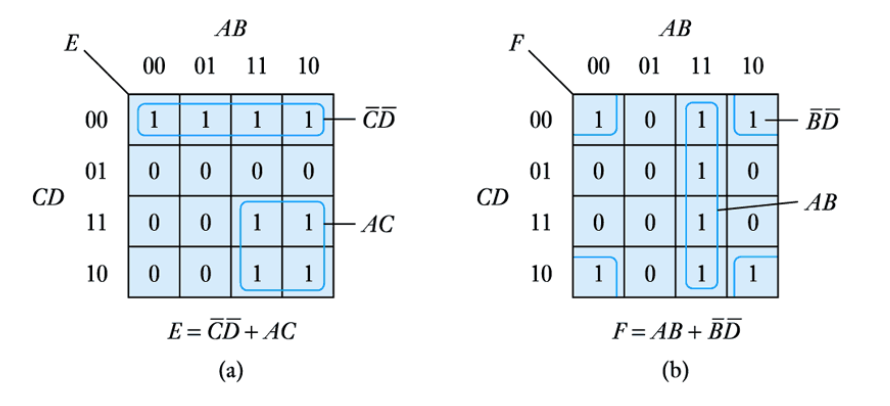
● Illegal groups
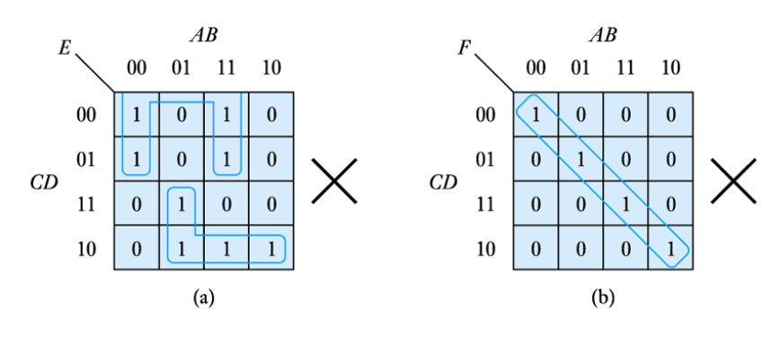
Examples of permitted groups of 2n elements
● It is often possibleto combine some '1's within more than one group – as shown
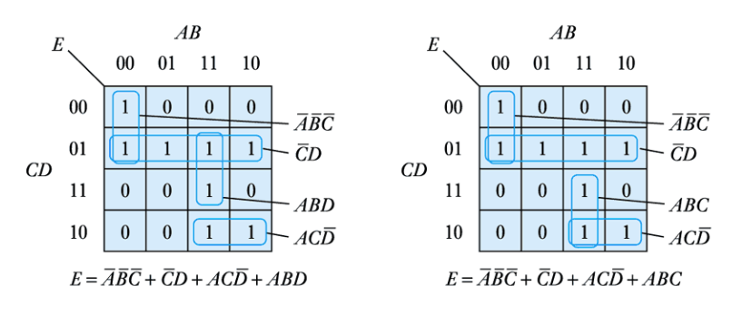
● This illustrates an important characteristic of Karnaugh maps - they are not unique
● When grouping '1's within a Karnaugh map we must follow certain rules. These are:
1. The largest possible groups of cells should be constructed first, each group containing 2n elements
2. Progressively smaller groups should be added until every cell containing a "1" has been included
3. Any redundant groups should then be removed, even if these are large groups, to avoid duplication
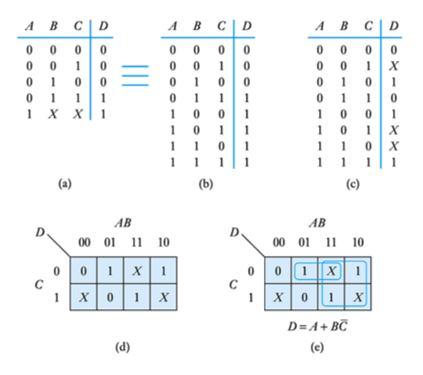
Example – see Example 24.12 in the course text
Simplify the following expression
D=\overline{A}B\overline{C}+AB\overline{C}+A\overline{B}\;\overline{C}+\overline{A}\;\overline{B}C+\overline[A}BC+ABC
This produces the following Karnaugh map
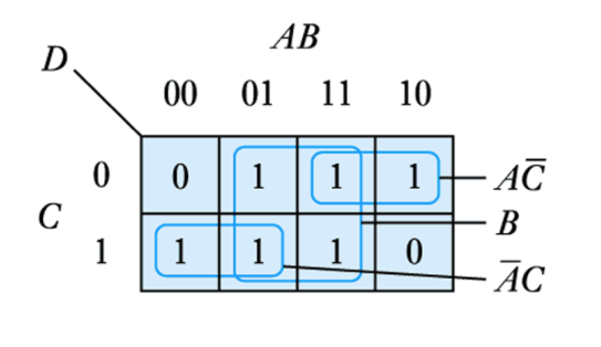
● Which gives
D=B+A\overline{C}+\overline{A}C
Example – see Example 24.13 in the course text
Simplify the following expression
E=\overline{A}B\overline{C}\;\overline{D}+AB\overline{C}\;\overline{D}+A\overline{B}\;\overline{C}\;\overline{D}+\overline{A}\;\overline{B}\;\overline{C}D+\overline{A}B\overline{C}D+AB\overline{C}D+A\overline{B}\;\overline{C}D+\overline{A}BCD+ABCD+\overline{A}BC\overline{D}+ABC\overline{D}
This produces the following Karnaugh map
E=B+A\overline{C}+\overline{C}D
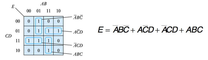
● Example – see Example 24.14 in the course text
● Simplify the following expression
E=\overline{A}B\overline{C}\;\overline{D}+\overline{A}B\overline{C}D+AB\overline{C}D+A\overline{B}\;\overline{C}D+\overline{A}\;\overline{B}CD+\overline{A}BCD+ABCD+ABC\overline{D}
● This produces the following Karnaugh map
● Karnaugh maps can be constructed for systems with more than 4 variables
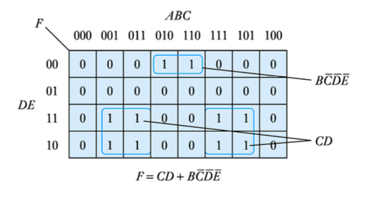
● However, as the number of variables increases the maps become unwieldy and other techniques are more appropriate
● Don‟t care conditions
– one of the strengths of Karnaugh maps is their ability to deal sensibly with don‟t care conditions
-
- Automated methods of minimisation
- ● Karnaugh maps can be used fairly easily with up to six variables
● For larger applications we normally use a tabular method known as Quine-McCluskey minimisation
– systematically attempts to simplify product pairs
- can be performed manually
- more often done by a computer -
- Propagation delay and hazards
- ● All physical logic gates take a finite time to respond to input signals and there is a delay between the time the input changes and when the output responds
● This is the propagation time delay
● This delay can cause problems. Consider this circuit
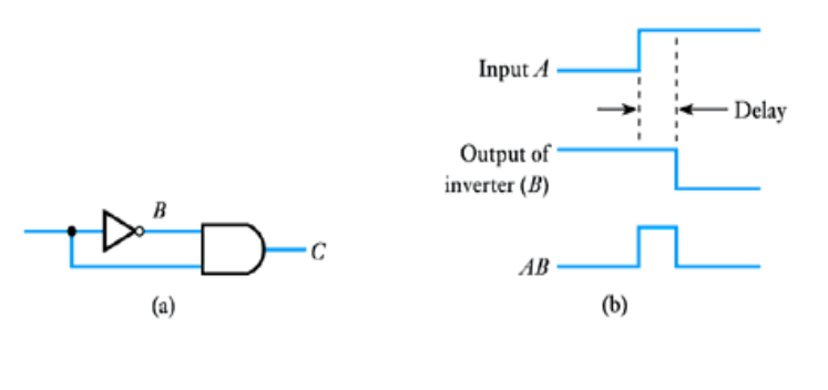
● The delay causes the output to differ from what we might expect
● This is an example of a hazard -
- Number systems and binary arithmetic
- ● Most number systems are order dependent
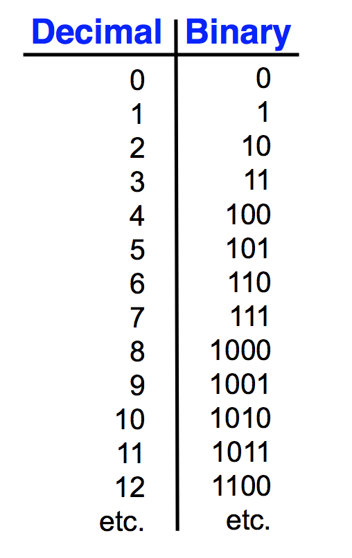
● Decimal
123410 = (1 x 10³) + (2 x 10²) + (3 x 101) + (4 x 100)
● Binary
11012 = (1 x 23) + (1 x 22) + (0 x 21) + (1 x 20)
● Octal
1238 = (1 x 83) + (2 x 82) + (3 x 81)
● Hexadecimal
12316 = (1 x 163) + (2 x 162) + (3 x 161)
here we need 16 characters – 0,1,2,3,4,5,6,7,8,9,A,B,C,D,E,F
● Number conversion
– conversion to decimal
● add up decimal equivalent of individual digits
Example – see Example 24.16 in the course text
Convert 110102 to decimal
110102 = (1 x 24) + (1 x 23) + (0 x 22) + (1 x 21) + (0 x 20)
= 16 + 8 + 0 + 2 + 0
= 2610
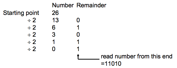
● Number conversion
– conversion from decimal
- repeatedly divide by the base and remember the remainder Example – see Example 24.17 in the course text Convert 2610 to binary
- Watch the Video 📹
- ● Binary arithmetic
– much simpler than decimal arithmetic
– can be performed by simple circuits, e.g. half adder
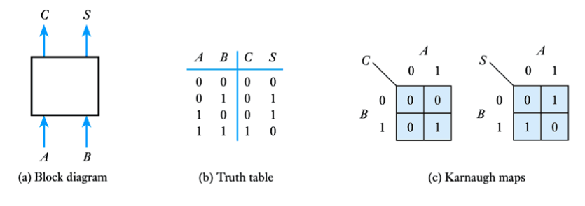
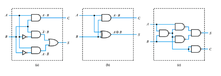
● Implementation of a half adder
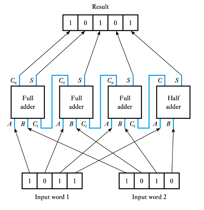
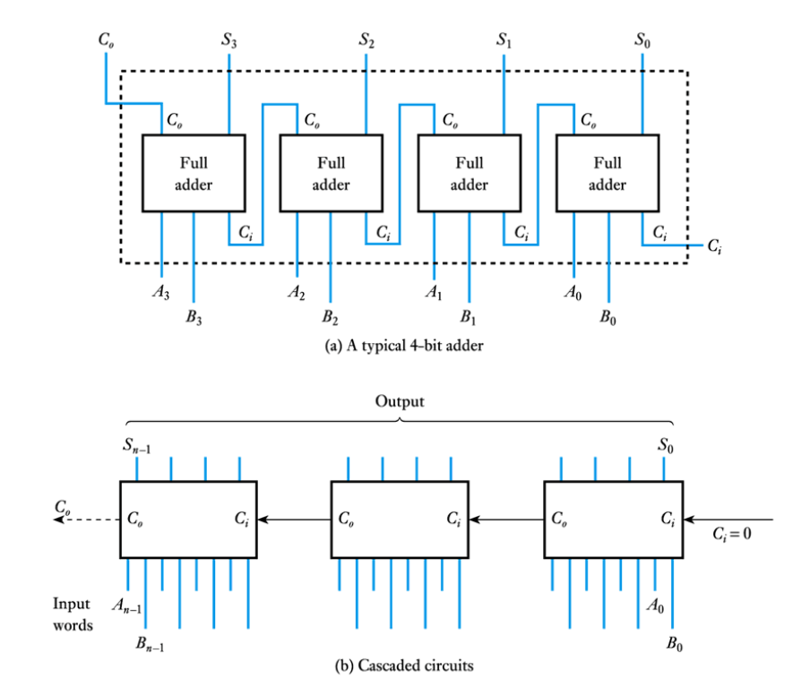
● Adding multiple-bit words
● A half adder can add two single bits
● To add multiple-bit words we also need a component that can also cope with a carry from the previous stage
● This is a full adder
● A full adder
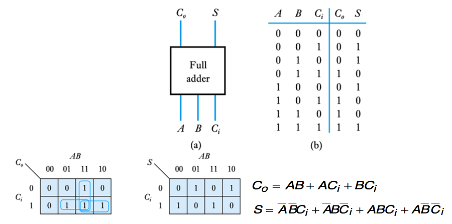
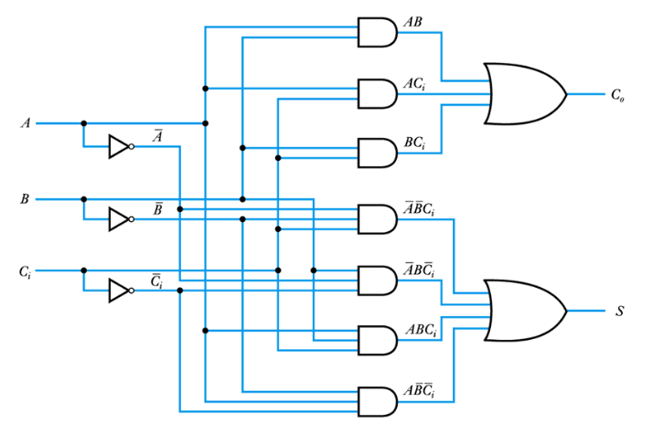
● Implementation of a full adder
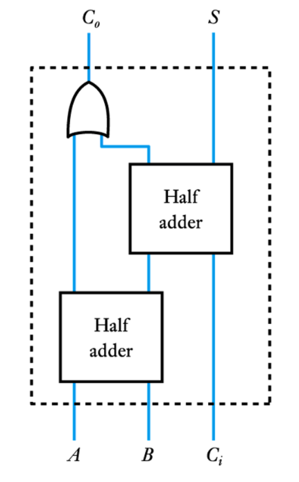
● Implementation of a full adder – from half adders
– produces a simpler circuit
– however, logical depth of the various outputs is not the same
– the two outputs will respond at slightly different times
● A cascadable 4-bit adder
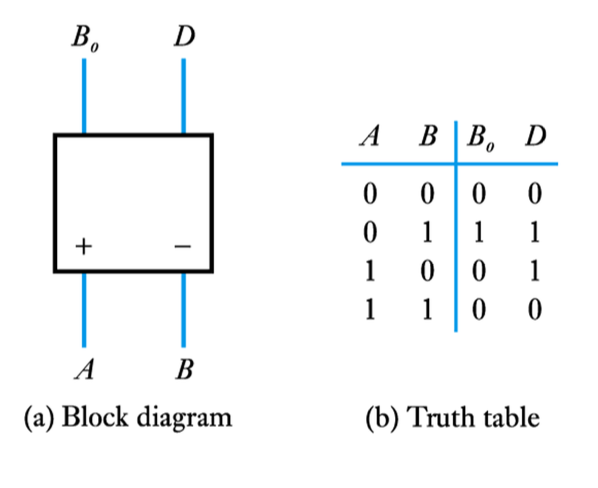
● Binary subtraction
– A similar approach can be applied to subtraction
– A half subtractor has two outputs called:
D difference
Bo borrow output
The inputs are also labelled + and – to show which is subtracted from which
● A 4-bit subtractor
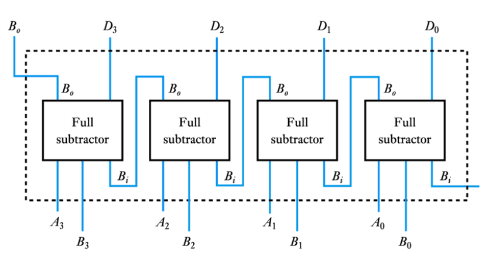
– These can be cascaded as with the adder circuits
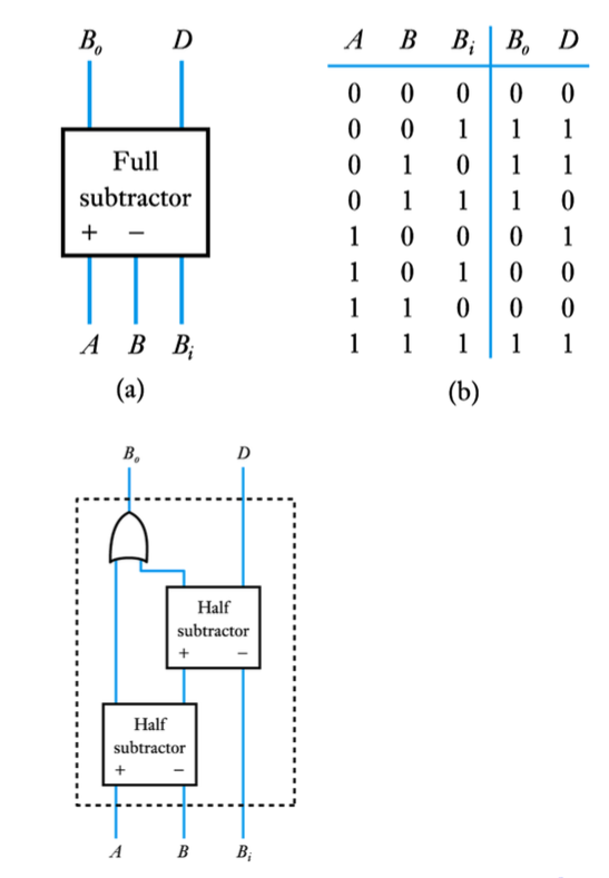
● A full subtractor
– these can be implemented directly
– or from two half subtractors
● Binary multiplication and division
– Although it is possible to construct circuits to perform multiplication and division using simple logic gates, it is fairly unusual as the complexity of the circuits makes them impractical
– It is more usual to use dedicated circuits containing large numbers of gates or to use a microprocessor
-
- Numeric and alphabetic codes
- Watch the Video 📹
- ● Binary code
– by far the most common way of representing numeric information
– has advantages of simplicity and efficiency of storage
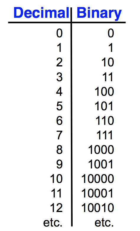
● Binary-coded decimal code
– formed by converting each digit of a decimal number individually into binary
– requires more digits than conventional binary
– has advantage of very easy conversion to/from decimal
– used where input and output are in decimal form
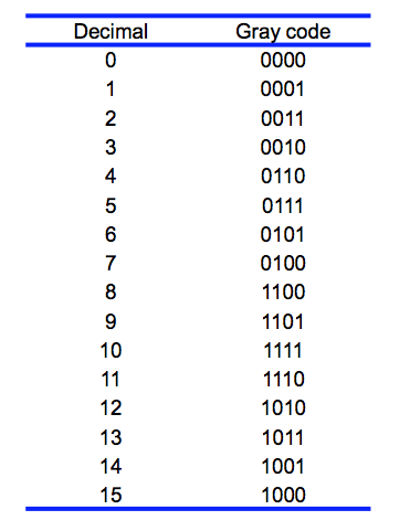
● Gray code
– used in Karnaugh maps
– also used in encoders and high-speed counters
– only one bit changes state between adjacent values
– allows counters/encoders to be read unambiguously
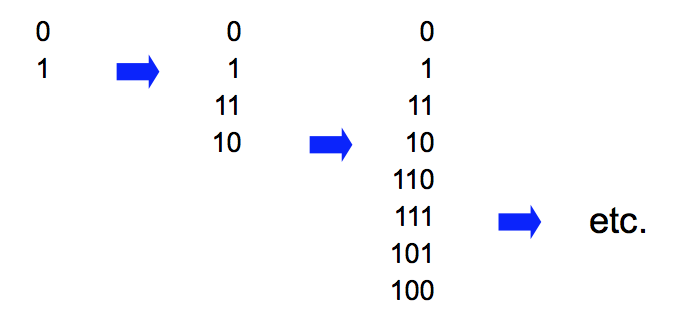
● Forming Gray code
– first write down the first two numbers (0 and 1)
– then repeat in reverse order with a 1 in front
– then keep repeating in reverse order with a 1 in front
-
- Examples of combinational logic design
- ● Example – see Example 24.25 in the course text
● Design a circuit to convert 3-bit binary numbers into Gray code
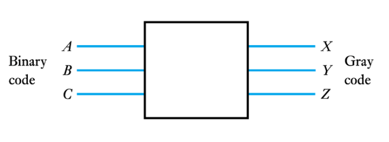
– First we produce a Truth Table
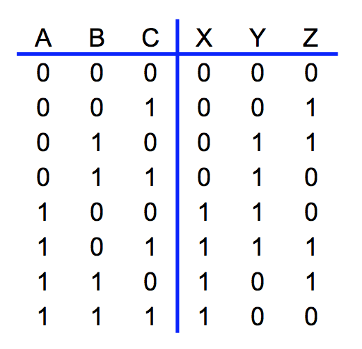
– From the truth table we produce Karnaugh maps
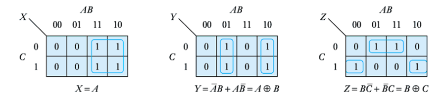
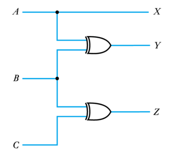
– and implement the circuit
● Example – see Example 24.26 in the course text
● Design a circuit to take a 4-bit number ABCD and produce a single output Y that is true if the input represents a prime number
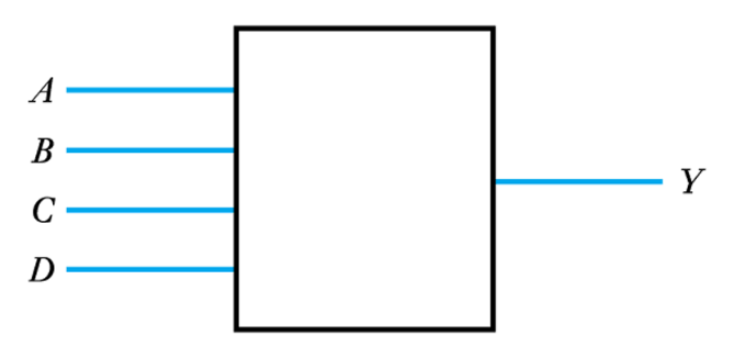
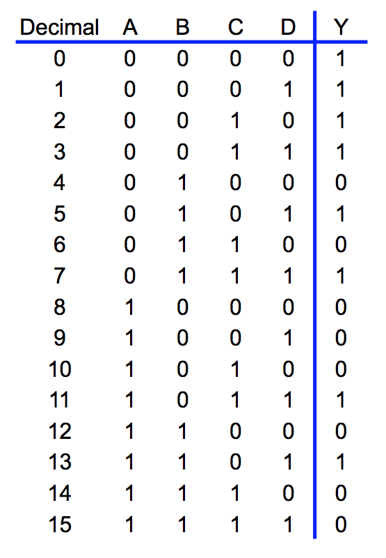
– Truth table
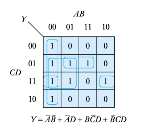
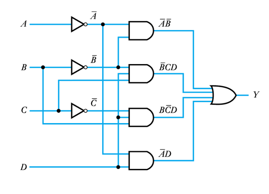
– Implementation
● Example – see Example 24.27 in the course text
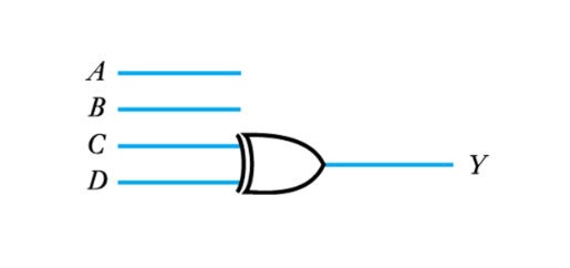
● Design a circuit to take a BCD number ABCD and produce a single output Y that is true only when the input corresponds to the numbers 1,2,5,6 or 9
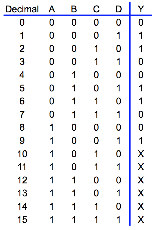
– Truth table
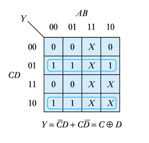
– Implementation
Common Cathode 7- segment Display
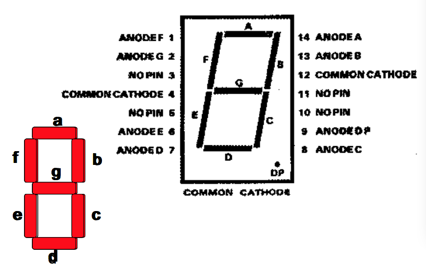
7- segment Display Decoding Logic
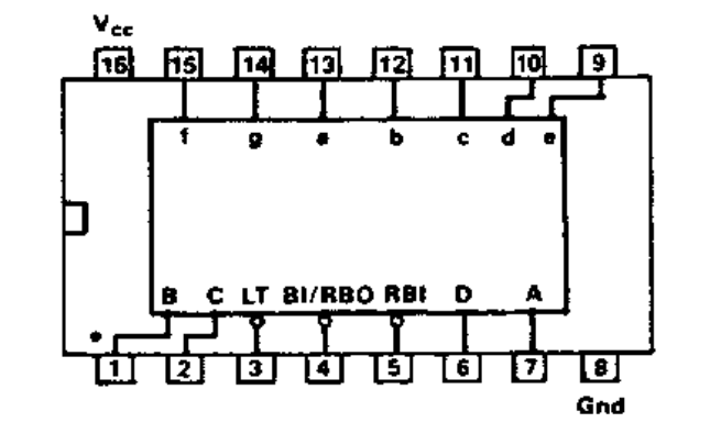
• 4 inputs pins, A, B, C and D to allow a binary equivalent for a decimal number between 0 and 9
• 7 output pins a, b, c, d, e, f, and g to drive each of the seven LED segments
• 3 pins (LT, BI/RBO and RBI) for testing purposes and multi-segment displays
• 2 pins for Power and Ground
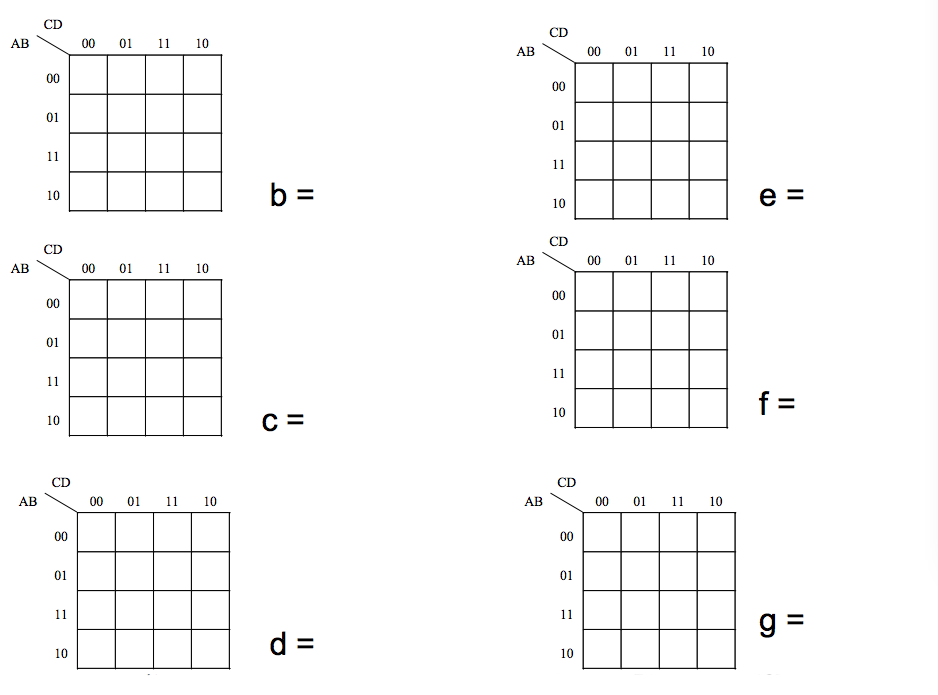
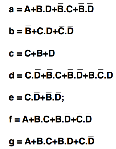
Find the “SOP” term to light segment 'a'
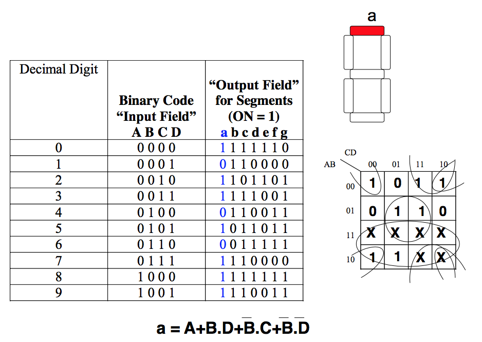
Don‟t assume these are correct!
-
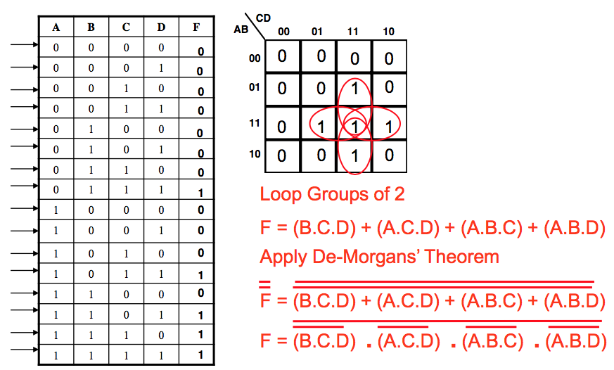
- Combinational Design Example
- A logic circuit is required that gives an output F = 1, when three or more of its four inputs (A,B,C & D) are high.
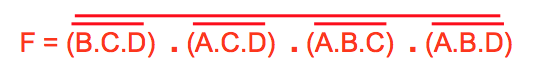
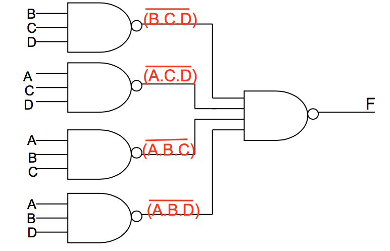
By completing the Truth Table and Karnaugh Map below, devise a logic solution using NAND gates only which will meet this specification.
- Circuit Design
-
-