09
-
- Sequential logic (Part 1)
- ● Introduction
● Bistables
● Asynchronous inputs
● Race hazards
● Master-slave flip-flop
● Counters
● Monostables
● Astables
● Memory registers
● Shift registers
-
- Introduction
- Watch the Video 📹
● Sequential logic elements combine the characteristics of combinational logic with memory
● When constructing sequential logic our building blocks are often some form of multivibrator
– A term used to describe a range of circuits
● these have two outputs that are the inverse of each other
● the output are labelled Q and \overline{Q}
– bistables
– monstables
– astables
-
- Bistables
- ● A regenerative switching circuit
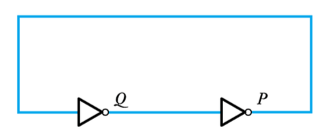
● This arrangement has two stable states
– It will stay in whichever state it finds itself
● It is a form of bistable – though not a very useful one
The S-R Latch
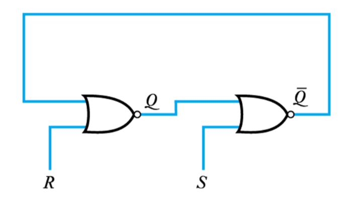
● Replacing the inverters with NOR gates produces a more useful circuit
–The circuit still has two stable states
–But now the inputs can switch it between these states
● The S-R latch (SET-RESET latch)
More often drawn like this
• when R = S = 0
–Circuit stays in current state
• when S = 1, R = 0
–Q is SET to 1 (\overline{Q} = 0)
• when S = 0, R = 1
–Q is RESET to 0 (\overline{Q} = 1)
• when S = 1, R = 1
–Both outputs at 0 – not allowed
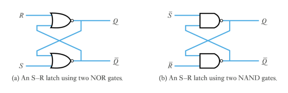
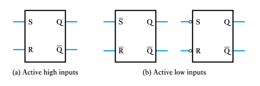
● An S-R latch can also be produced using NAND gates
–produces an active-low circuit
● S-R latch logic symbols
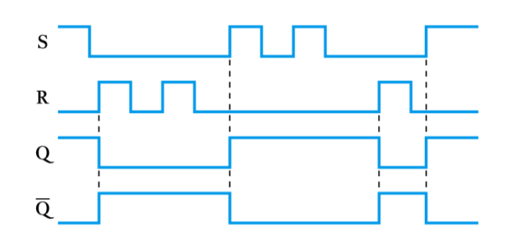
● Sample input and output waveforms for an S-R latch
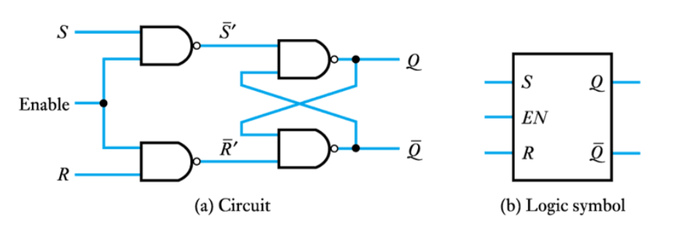
● The gated S-R latch
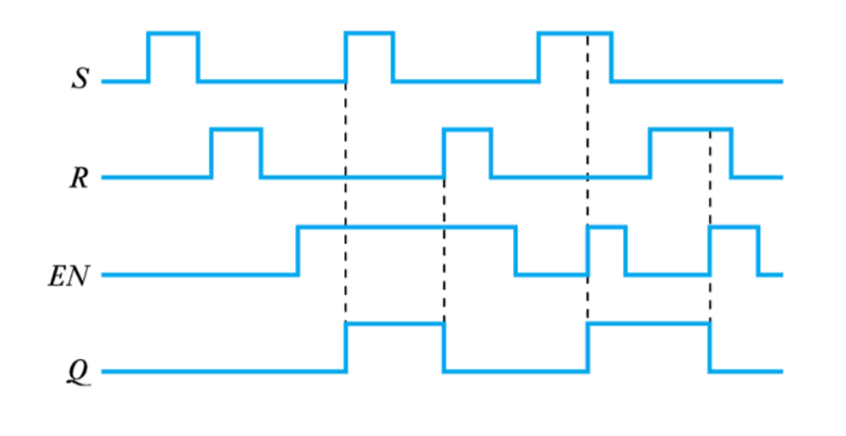
● Sample input and output waveforms for a gated S-R latch
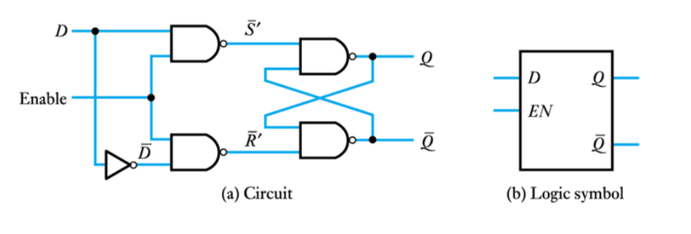
● The D latch
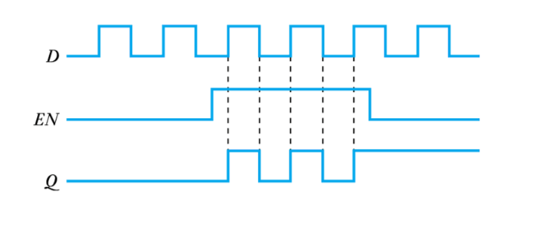
● Sample input and output waveforms for a D latch
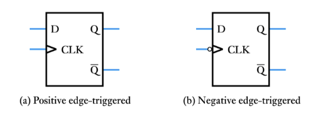
Edge-triggered devices
–It is often necessary to synchronise many devices
–This can be done using a clock input
• such devices respond on a particular transition of the clock.
• these are called edge-triggered devices or flip-flops
• can have positive-edge or negative-edge triggered devices
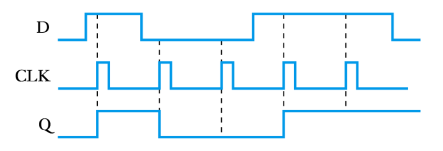
● The D flip-flop
–Symbol as in previous slide
–Behaviour of positive-edge triggered device as below
–Q becomes equal to D at the time of the trigger event
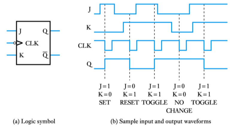
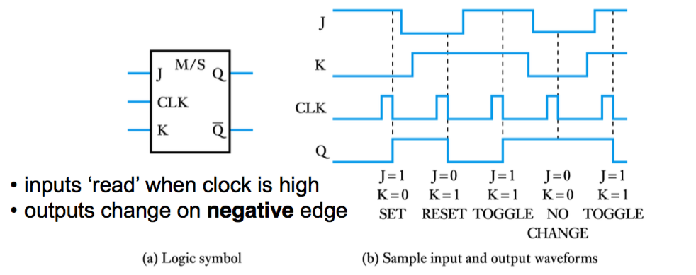
● The J-K flip-flop
– Similar to S-R flip-flop but toggles when J = K = 1
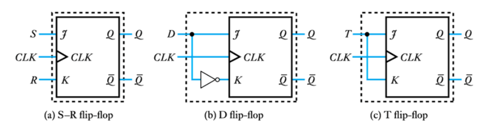
● Use of a J-K flip-flop to reproduce other flip-flop functions
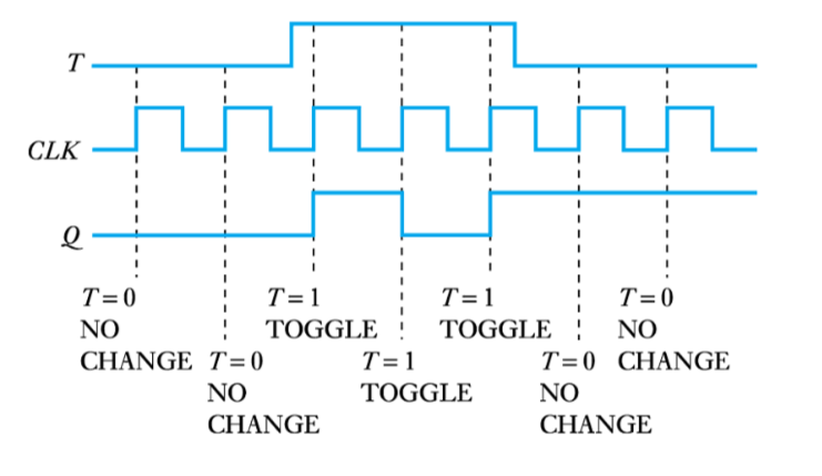
● Typical waveforms for a positive edge-triggered T flip-flop
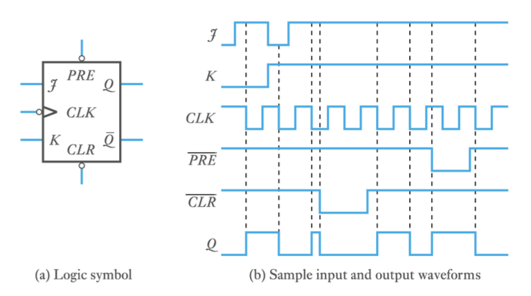
● Asynchronous inputs
– Some flip-flops have asynchronous inputs
● Propagation delays and races
–Real logic gates take a finite time to react
–Some circuits (as below) can suffer from race hazards where the operation of the circuit is uncertain
• In this circuit the output depends on which devices is fastest
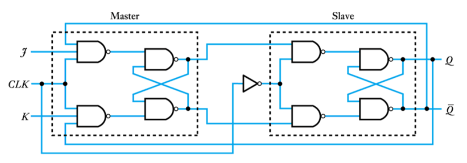
● Pulse-triggered or master/slave bistables
These overcome race hazards by responding to the state of the inputs shortly before the clock trigger
● Circuit of a basic J-K master/slave flip-flop
-
- Key points
- ● Sequential logic circuits have the characteristic of memory
● Among the most important groups of sequential components are the various forms of multivibrator
–bistables
–monostables
–astables
● The most widely used form is the bistable which includes –latches, edge-triggered flip-flops and master/slave devices -