Wk 9
- Bevel Gears
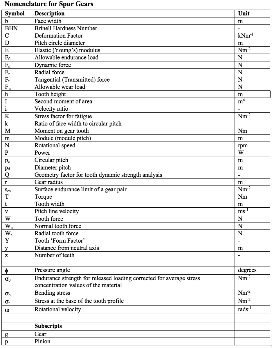
– Worm and a worm wheel– Transmit motion between non-parallel non-intersecting shafts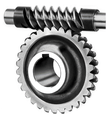
Gear Motion
- Basic Gear Motion

- Gear Motion Showing Pitch Circles


Gear Motion and Construction
- Introduction Overview of types
- Gear Motion
- Terminology
- Involute Gear Construction
- Materials
- Material Selection
Introduction
- Spur Gears
– Teeth parallel to the axis of rotation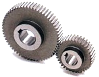
- Helical Gears
– Teeth inclined to the axis of rotation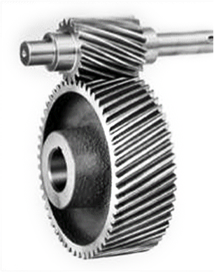
- Bevel Gears
– Teeth formed on conical surfaces– Transmit motion between intersecting shafts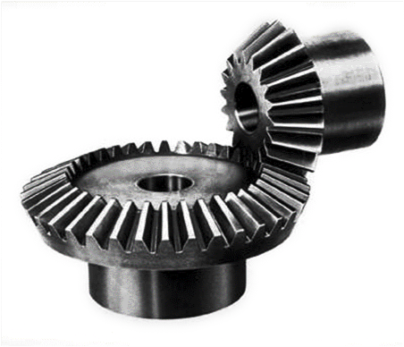
- Bevel Gears
-
Terminology
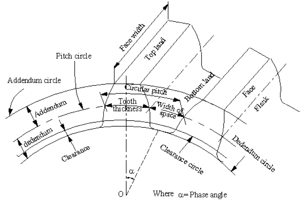
- 📷 Terminology diagram can be seen larger by clicking here
Pinion: a pinion is the smaller of two mating gears. The larger is often called the gear or the wheel.
Pitch circle: it is an imaginary circle, which by pure rolling action would give the same motion as the actual gear.
Pitch circle diameter: it is the diameter of the pitch circle. The size of the gear is usually specified by the pitch circle diameter. It is also called as pitch diameter.
Pitch: pitch of two mating gears must be same, it is defined as follows:
Circular pitch (p$ _{\textbf c} $): It is the distance measured along the circumference of the pitch circle from a point on one tooth to the corresponding point on the adjacent tooth,
- Circular Pitch $ \ p _c = \frac{\pi D}{z} $
Where, D = Diameter of pitch circle, and z = Number of teeth on the wheel.
Diameter pitch (p$ _{\textbf d} $): It is the ratio of teeth to the pitch circle diameter.- Diameter Pitch $ \ p _d = \frac{z}{D} = \frac{\pi}{p _c} $
Module pitch (m) It is the ratio of the pitch circle diameter to the number of teeth.- Module $ \ m = \frac{D}{z} $
Addendum circle (or tip circle): it is the circle drawn through the top of the teeth and is concentric with the pitch circle.
Addendum: it is the radial distance of a tooth from the pitch circle to the top of the tooth. Dedendum circle (or root circle): it is the circle drawn through the bottom of the circle.
Dedendum: it is the radial distance of a tooth from the pitch circle to the bottom of the tooth.
Clearance: it is the radial distance from the top of the tooth to the bottom of the tooth, in a meshing gear. A circle passing through the top of the meshing gear is known as clearance circle.
Total depth: it is the radial distance between the addendum and the dedendum of a gear. Total depth = addendum + dedendum
Working depth: it is the radial distance from the addendum circle to the clearance circle. It is equal to the sum of the addendum of the two meshing gears.
- Continues on next tab
-
Terminology (cont.)
- 📷 Terminology diagram can be seen larger by clicking here
Tooth thickness: it is the width of the tooth measured along the pitch circle.
Tooth space: it is the width of the space between the two adjacent teeth measured along the pitch circle.
Backlash: it is the difference between the tooth space and the tooth thickness along the pitch circle. Backlash = tooth space – tooth thickness.
Face width: it is the width of the gear tooth measured parallel to its axis.
Top land: it is the surface of the top of the tooth.
Bottom land: the surface of the bottom of the tooth between the adjacent fillets.
Face: tooth surface between the pitch circle and the top land.
Flank: tooth surface between the pitch circle and the bottomland including fillet.
Pressure angle $\phi$: it is the angle between the common normal to two gear teeth at the point of contact and the common tangent at the pitch point. The standard pressure angles are 14.5° and 20°.
Velocity ratio: it is the ratio of speed of driving gear to the speed of the driven gear. Where N$_A$ and N$_B$ = speeds of driver and driven respectively, and z$_A$ and z$_B$ = number of teeth on driver and driven respectively.
- Velocity Ratio $ \ i = \frac{N_A}{N_B} = \frac{z_B}{z_A} $

- Significance of Pressure Angle
– Determines:
Thickness of the tooth at its root and therefore its strengthLength of the contact on the flanks of the mating teeth and therefore the wear on the teethNumber of teeth on a small wheel before interference occursResultant pressure on the shafts, as will be seen from the force equations for each of the gear types
- Formulae for Tooth Dimensions for Pressure Angles of 20$^0$ and 25$^0$
Quantity Formula Addendum a = m Dedendum b = 1.25.m Working depth h$ _{\textbf{k}} $ = 2.m Whole depth (min) h$ _{\textbf{t}} $ = 2.25.m Tooth thickness t = m/2 Clearance (min) c = 0.25.m Width of top land t$ _{\textbf{o}} $ = 0.25.m Base circle diameter D$ _{\textbf{b}} $ = m.z.cos $\phi$
- Selection of Module (mm) for Pressure Angles of 20$^0$ and 25$^0$
Preferred 1, 1.25, 1.5, 2, 2.5, 3, 4, 5, 6, 8, 10, 12, 16, 20, 25, 32, 40, 50 Next choice 1.125, 1.375, 1.75, 2.25, 2.75, 3.5, 4.5, 5.5, 7, 9, 11, 14, 18, 22, 28, 36, 45

Involute Gear Construction
- Advantages
– Variation in the centre distance does not affect correct tooth meshing
– Involute teeth can be generated by the use of the simplest type of cutters, namely straight-sided rack cutters
– They can also be generated by pinion-type cutters and by hobs so that production is not limited to any one type of gear-cutting machine
– All gears cut with the same cutter will correctly intermesh
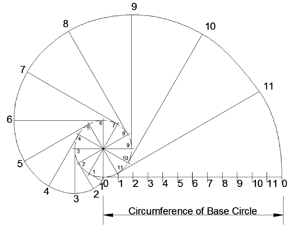
- 📷 Circumference of base circle diagram can be seen larger by clicking here
- Teeth
– Minimum Number $ z_{max} = 2/ sin^2 \phi $
– Width of Tooth Face
Issues with narrow teeth < 2.5p$ _{\textbf{c}} $. Poor resistance to shock loads
. Will not absorb vibration as well as a wider one
– For good rigidity b/D < 1:12
- Significance of Pressure Angle
Material Selection
- The selection of the gear material depends upon:
– Type of service
– Peripheral speed
– Method of manufacture
– Degree of accuracy required
– Wear and shock resistance
– Cost of the material
– Space and weight limitations
– High loads, impact loads, and longer life requirements
– Safety and other considerations
Gear Materials
- Metallic Materials
– Steel
– Cast Iron
– Bronze
- Steel
– Most widely used material in gear manufacture
– Heat treatment combines property of toughness with hardness
– Hardness
Brinell Hardness < 350 used for light and medium duty drivesBrinell Hardness > 350 used for heavy drives and tight locations- Cast Iron
– Low cost
– Good machinability
– Moderate mechanical properties
– Large size gears made of grey cast iron
- Bronze
– Used in worm gear drives due to ability to withstand heavy sliding loads
– Also used for corrosion and wear resistance applications
- Non-metallic Materials
– Wood
– Rawhide
– Compressed paper
– Synthetic resins, e.g. nylon
 TENSILEpulling/stretching
 COMPRESSIVEpushing/squeezing
 BENDINGflexure
 SHEARsliding
 THERMALexpansion/contraction with change in temperatureo
- The selection of the gear material depends upon:
- Alternative Transmitted/Tangential Load Calculation
– Pitch Line Velocity
$$ \large v = \frac{\pi dN}{60} $$– Rotational Speed
$$ \large \omega = v \ / \ r = 2v \ / \ d $$– Torque
$$ \large T = \frac{d}{2} \times F_t $$- Alternative Transmitted/Tangential Load Calculation
– Remember that:
$$ \large P = T \times \omega $$– Therefore:⬇ Worked Example - Spur Gear Force Analysis
$$ \begin{align*} \large P = \frac{d}{2} \times F_t \ \times \ v \ \times \frac{2}{d} \end{align*}$$ $$ \large \Rightarrow P = F_t \ \times \ v $$ $$ \large \Rightarrow F_t = \frac{P}{v} $$
Spur Gears
Outline
- Gear Force Analysis
- Spur Gear Forces
– Worked Examples
Gear Force Analysis
- Required to determine gear affect on shaft and bearings
- Generally determined as components
– Tangential
– Radial
– Axial
- Can be added as vector sum
- System considered 100% efficient due to negligible friction losses
– Epicyclic gear systems and worm and worm gear systems exceptions to this
Spur Gear Force Analysis
- Tangential (Transmitted) Force
$$ \large \ F _t = \frac{T}{r} $$- Radial Force
$$ \large \ F _r = F_t \ \text{tan} \ \phi $$- Where:
$$ \large \ T = \frac{60 \times P}{2 \pi N} $$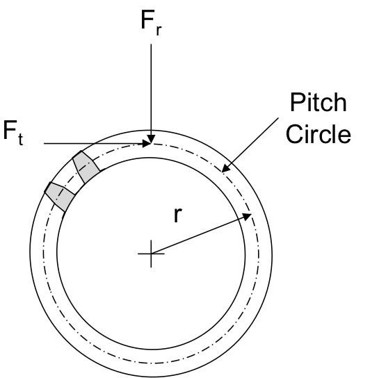 TENSILEpulling/stretchingCOMPRESSIVEpushing/squeezingBENDINGflexureSHEARslidingTHERMALexpansion/contraction with change in temperatureo
- Alternative Transmitted/Tangential Load Calculation
- 📷 Table: Lewis Form Factor, Y (for pressure angle of 20$ ^0$ – adapted from Hall et al, 1980)
– Barth’s Equation
Allowable $ \large \sigma_t = \sigma_0 \bigg(\frac{3}{3+v} \bigg) \ for \ v < 10 \ ms ^{-1} $ $ \large \quad \quad \quad \quad = \sigma_0 \bigg(\frac{6}{6+v} \bigg) \ for \ 10 \ v < 20 \ ms ^{-1} $ $ \large \quad \quad \quad \quad= \sigma_0 \bigg(\frac{5.6}{5.6+\sqrt{v}} \bigg) \ for \ v > 20 \ ms ^{-1} $
- Lewis Equation
– Modified Form
$$ \large F_t = \sigma _t kYp^2_c = \sigma _t \pi^2 kYm^2 $$ where:
$$ \large b = kp_c \quad k \leq 4 $$– For known pitch diameter
$$ \large \frac{1}{Ym^2} = \frac{\sigma_tk\pi^2}{F_t} $$– For unknown pitch diameter
$$ \large \sigma_t = \frac{2T_p}{\pi^2kYm^3z_p} \leq Equation (2.16) $$
Typical Value Ranges of $ \large \sigma \small _0$ for Common Materials
Material $ \sigma _0$ (MPa) Bronze 83 (Hall et al, 1980) Carbon Steel 70 – 350 (Hall et al, 1980) Cast Iron 55 (Hall et al, 1980)
71 – 161 (Shigley, 1986)
⬇ Worked Example - Spur Gear Tooth Stress Analysis
Stresses in Gear Teeth
Outline
- Stresses in Spur Gear Teeth
– The Lewis Equation
Strength of Gear Teeth– Buckingham Equations
Design for Dynamic Tooth Load and Tooth Wear– Worked Examples
- Primary Considerations
– Material Type
– Face Width
– Module
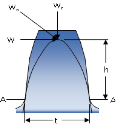
- Lewis Equation Derivation
– Bending Stress EquationWhere:$$ \large \sigma _b = \frac{My}{I} $$$$ \large M = Wh$$$$ \large y = t \ / \ 2$$$$ \large I = bt^3 \ / \ 12 $$$$ \large \sigma = Wh \ \times \ \frac{t}{2} \ \times \ \frac{12}{bt^3} \ = \ \frac{6Wh}{bt^3} $$- Lewis Equation
– Usual Form
$$ \large F_t = \sigma _t bYp_c $$ where:
$\large \sigma _t$ = the stress at the base of the tooth profile (Nm $^{-2}$)
– ‘form factor’ Y
$$ \large Y = t^2 / 6hp_c $$ 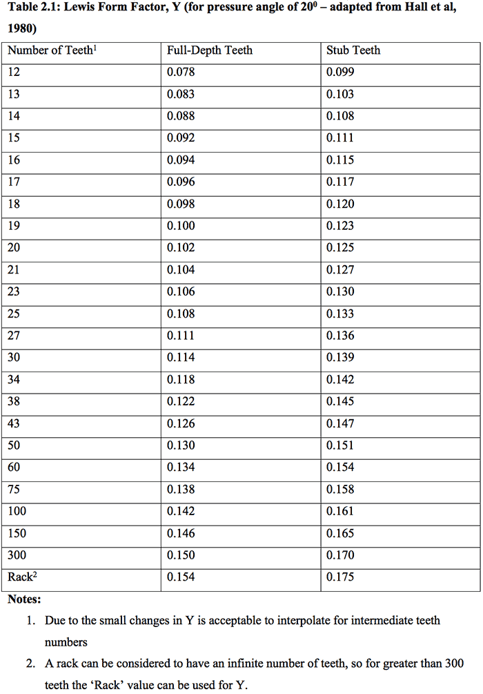
- 📷 Table: Lewis Form Factor, Y (for pressure angle of 20$ ^0$ – adapted from Hall et al, 1980)
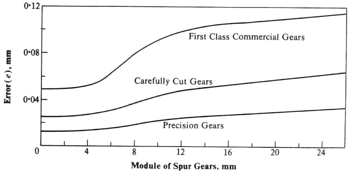
- Error vs Module (Hall et al, 1980)
- Allowable Endurance Load
$$ \large F \small _0 \large = \sigma \small _0 \large bYp_c $$- Allowable Tooth Wear Load
$$ \large F \small _w \large = D \small _p \large bKQ $$ Where: $ \large Q = 2z_g \ / \ \bigg(z_p + z_g\bigg) $
$ \large \quad \quad \quad \quad K = \cfrac{s^2_{es} \ sin \phi \bigg( 1/E_p + 1/E_g \bigg)}{1.4} $
$ \large \quad \quad \quad \quad s_{es} = 2.75(BHN) - 70 $
Design for Dynamic Load and Wear
- Causes of Dynamic Loads
– Defects in the tooth profile
– Inaccuracies in gear spacing
– Mounting misalignment
– Tooth deflection under load
- Buckingham Equation $$ \large F_d = \frac{21v\bigg(bC + F_t \bigg)}{21v + \sqrt{\bigg(bC + F_t \bigg)} } + F_t $$
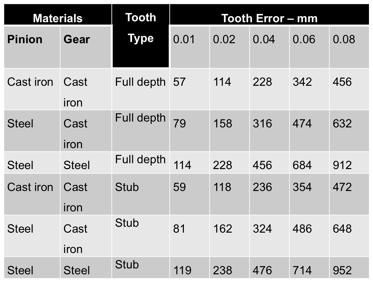
- Values of Deformation Factor, C, in kNm $^{-1}$ (adapted from Hall et al, 1980)
- Interpolation Calculation for Deformation Factor Video
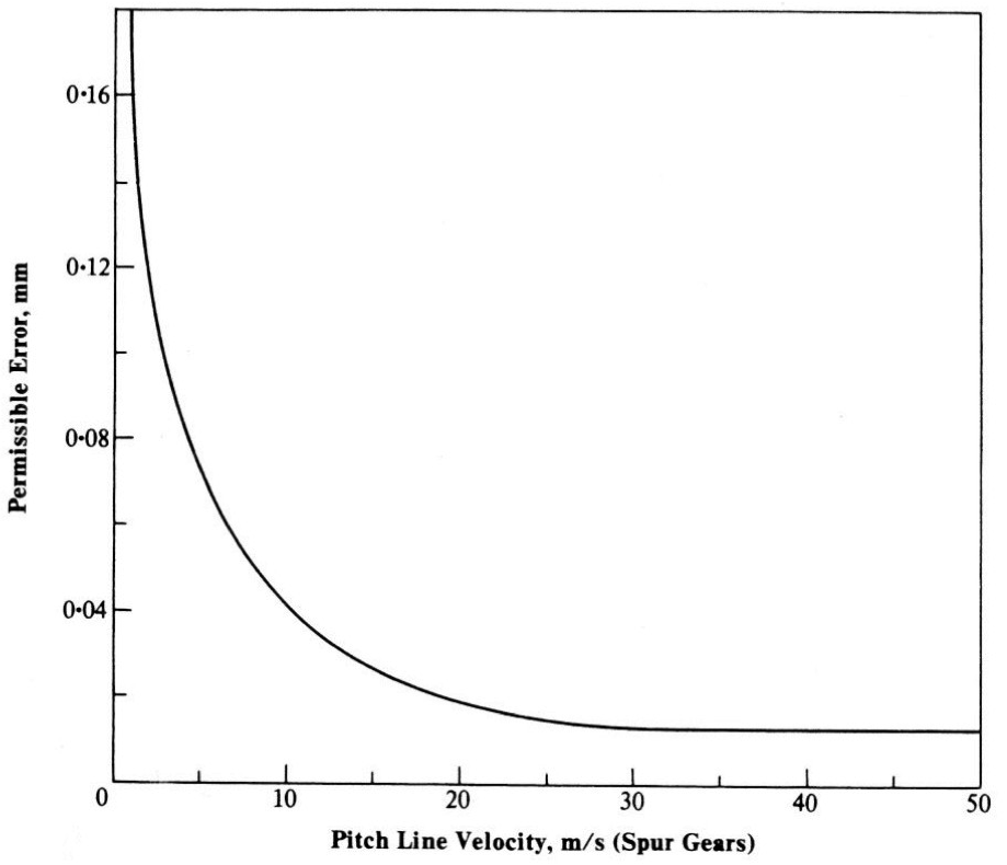
- Permissible Error vs Pitch Line Velocity (Hall et al, 1980)

- Error vs Module (Hall et al, 1980)
-

Tutorial A
- ⬇ Spur Gear Tutorial A
-

Tutorial B
- ⬇ Spur Gear Tutorial B