-
Introduction to High Voltage (HV) Technology, Electric Field Theory and Simple HV Design
Learning objectives:
• To introduce the fundamental concepts in high voltage technology.
• To introduce the different insulating materials and power plant items used in power systems.
• To understand the definition of electric field, electric stress, and electric strength of an insulating material.
• To learn the effect of a dielectric or insulating material on electric field, particularly the interface between materials of different permittivity
• To learn Gauss’s Law and application to a co-axial cable
• To learn the field distribution and non-uniform voltage distribution in plant design, to develop understanding of measures for stress controls
Prof. Chengke Zhou
Email: c.zhou@gcal.ac.uk -
Wk 1 - Introduction to HV power systems
Modern power systems consist of systems of power generation, power transmission, power distribution and power utilisation, as shown in Figure 1. Two factors considered in classifying a voltage as "high voltage" are the possibility of
– causing a spark in air,
– and the danger of electric shock by contact or proximity.
The definitions may refer to the voltage between two conductors of a system, or between any conductor and ground or earth.
In electric power transmission engineering, high voltage is usually considered any voltage over approximately 35,000 volts. This is a classification based on the design of apparatus and insulation.
The International Electrotechnical Commission (IEC) and its national counterparts (IET, IEEE, etc.) define high voltage as above 1000 V for alternating current, and at least 1500 V for direct current and distinguish it from low voltage (50 to 1000 VAC or 120–1500 VDC) and extra low voltage (<50 VAC or <120 VDC) circuits. This is in the context of building wiring and the safety of electrical apparatus.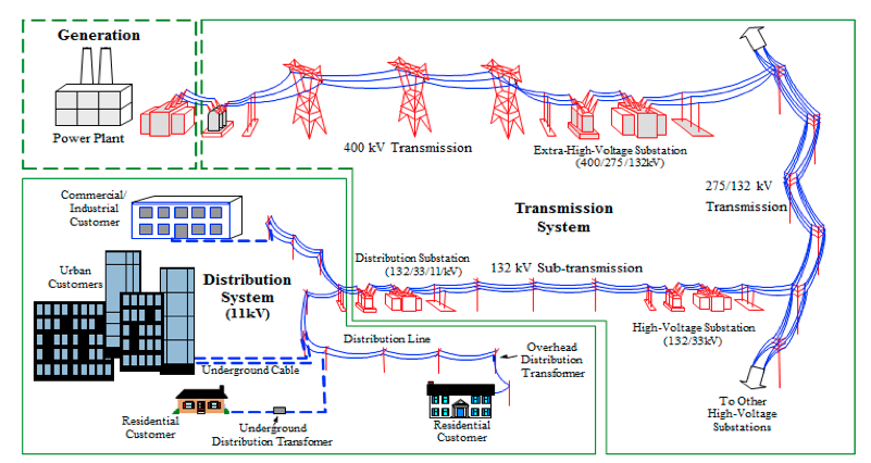
Fig. 1 In power system in the UK, power is usually generated at a level of 11kV at large power stations. Power generated is then transmitted to load centre at voltage levels of 400/275/132kV. Power distribution voltage levels include mainly 33kV and 11kV. The distribution transformers reduce the voltage to 400V/230V, which supplies the houses, shopping centres, etc.
Power systems operating at high voltages lead to lower losses. So far, HVAC (alternating current) reached 800kV in parts of the world.
HVAC systems enjoy the advantage of:
• easy transformation of energy between different voltage levels,
• mature technology
Disadvantages include
• transmission and compensation of reactive power,
• stability problems
In recent years, there has been increasing adoption of HVDC (direct current) due to the advantages such as:
• No (capacitive) charging currents
• No stability problems (frequency)
• Higher power transfer
• No inductive voltage drop
• No Skin-Effect
• High flexibility and controllability
The use of higher voltages introduces a number of challenges in the design, maintenance and operation of the power systems. In general all metals are conductors, but conductors of electricity in power equipment are made with copper and aluminium as they are the cost-effective choices. Non-metals are generally non-conductors of electricity, i.e. insulating materials. In power systems, these include gases in their non-ionized state – air at atmospheric pressure being the most generally applied. Pure, deionised water is also an insulating material, but small quantities of dissolved inorganic salts turn it into a conductor, despite the fact that the salt crystals are insulators when dehydrated. Organic matter, such as wood, is also a good insulator when dry, but becomes conducting when moist. The properties of a number of substances are given in Table 1.1. From this table air at atmospheric pressure is an obvious choice as an insulating material.
The use of air as insulation resulted in the widespread use of high voltage overhead lines and outdoor substations. It is however still necessary to support the high voltage conductors mechanically. For this purpose porcelain and glass have given good service as support or suspension insulators. These insulators then appear electrically parallel to the air insulation that surrounds the bare conductor. The interface between the porcelain or glass and air turns out to be a vulnerable region. In power systems insulation systems should be able to perform reliably under normal voltage conditions as well as under abnormal overvoltage conditions, hence testing and monitoring of the condition of equipment become important topics.
Table1:Properties of conductors and insulating materials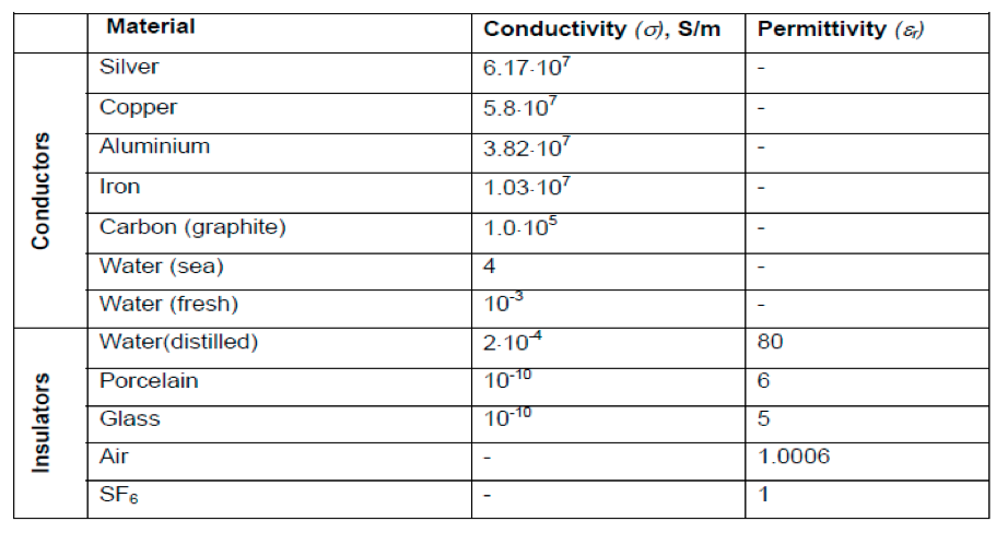
-
HV plant items in power systems
- Generator
Large generator voltage is typically between 10 and 25 kV. The insulation of the stator bars relative to the stator slots poses a particularly difficult insulation problem in the light of the limited space, high voltage and temperature.
Mica, bonded with epoxy resin is usually applied as insulation material. Further details on generator insulation will be provided in Lecture 3.
- Substations
The substations are the nodes in the power system where incoming and outgoing power lines and transformers are connected together as is shown in Fig. 1. In power substations the voltage may be raised to the levels of the transmission system and stepped down again to lower distribution levels when appropriate, via the use of transformers (to be covered later in the module). Typically, distribution stations operate at voltages of 132 kV (UK) and below to distribute the power to the points of consumption. Circuit breaker is an important part in substations. In recent years, indoor gas-insulated substation (GIS) has seen increasing use. In GIS the use of SF6, a gas with exceptional insulating properties, facilitates the design of very compact substations. In GIS a co-axial tubular system may be used and all the components, such as isolators and circuit breakers form an integral part of the substation.
Further about substation with visual aids can be found at this link Electrical Engineering Portal
• Circuit breakers (CB) and isolators
The incoming and outgoing circuits can be designed to switch to either of the two busbars by means of the busbar selection isolators. Isolators are also provided on both sides of equipment such as transformers and circuit breakers to allow disconnection during maintenance of the equipment. Isolators are not designed to interrupt full load or fault currents and should only be operated under no-load conditions. Circuit breakers differ from the isolators in that they can interrupt full load and fault currents. CBs are categorised by the insulation medium used in the inside chamber. These include oil CB, SH6 CB, Vacuum CB, Air Blast CB etc.
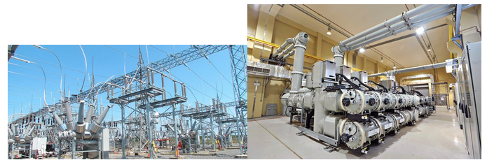
Figure 1 An outdoor (left) and an indoor (right, gas insulated) HV substation
- Overhead Lines, cables and gas-insulated lines
Overhead Lines, cables and gas-insulated lines form important parts of power transmission and distribution systems. Their role is to transmitting power from one location to another.
Overhead lines have the following properties and advantages:
• Insulating Material: Air
• High voltages are easy to handle with sufficient distances/clearances and lengths
• Permitted phase wire temperature of phase wires is high
• Overhead lines are defined by their natural power rating PNat
• Thermal Power limit is a multiple of PNat
• Simple and straightforward layout, (Relatively) easy and fast to erect and to repair
• Large load capacity and overload capability
• Lowest (capacitive) reactive power of all systems
• Long physical life, Lowest investment costs, Lowest unavailability
Disadvantages of overhead lines:
• High failure rate (most failure are arc failures without consequences)
• Impairment of landscape (visibility)
• Low electromagnetic fields can be achieved through distances and arrangements
• Highest losses
• Highest operational costs because of current-dependent losses
Power cables have the following properties:
• Insulating Materials: Plastics/Synthetics (PE, XLPE), Oil – Paper
- Polypropylene Laminated Paper (PPLP): reduced power loss and higher electrical strength than oil-paper cables
• Cables have a high capacitance, large capacitive currents, limits maximum (cable) line length
• Transferable power is limited by:
- permitted temperature of the dielectric
- high thermal resistances of accessories & auxiliary equipment
- soil condition
• Thermal Power Stherm is essential for continuous rating/operation
• High voltage cables have a much higher Pnat than Stherm (of about 2...6)
Advantages
• Large load capacity possible with thermal foundation and cross-bonding
• Lower impedances per unit length when compared to overhead lines
• Lower failure rate than overhead lines
• No electrical field on the outside
• Losses are only 50% of an overhead line
• Operational costs (including losses) are about half of the costs of an overhead line
Disadvantages are:
• High requirements to purity of synthetic insulation and water- tightness
• Overload only temporary possible, otherwise influences lifespan of insulation
• High reactive power, compensation necessary
• Unavailability is notable higher when compared to overhead lines (high repairing efforts)
• Lifespan: 30 to 40 years (assumed)
• Extensive demand of space, drying out of soil, only very limited usage of line route possible
• 3-6 times investment costs compared to overhead lines
For GIL, properties include:
• Insulating Material: SF6 and N2: Currently 80% N2 and 20 % SF6; pressure: 3 to 6 bar
• Currently no buried lines; laying only in tunnels or openly
• Many flanges necessary
• Compensation of (axial) thermal expansion of ducts
• SF6: Environmental compatibility is a problem
• Requires gas monitoring
Advantages:
• High transmission capacity
• large overload capability
• Minimal dielectric losses
• Low mutual capacitance → low charging current / power
• Good heat dissipation to the environment
• Large transmission capacity
• High load capacity
• High overload capability
• Lower impedance per unit length than overhead lines
• Low failure rates
• High lifespan expected (Experience with GIS)
• No ageing
• Lowest electro-magnetically fields
• Lower losses than cables
• Lower operational costs (including losses) than cable lines
Disadvantages of GIL include:
• High Requirements to purity and gas-tightness
• Higher reactive power than overhead lines
• Gas monitoring, failure location, PD-monitoring
• Higher unavailability than cables because of long period of repair
• Short operational experience, only short distances in operation
• Large sections necessary, only limited usage of soil possible, issues with SF6
• Investment costs 7-12 times higher when compared to overhead lines
- Power transformers
The power transformers change the voltage from one level to another and must be able to handle the full power to be transformed, i.e. the copper windings must be rated to handle the full load current and short time overcurrents. The magnetic circuit and insulation must be able to cope with the rated system power, voltage, and to allow for overvoltages. The copper windings must be adequately insulated to prevent insulation failure to the earthed iron core, between windings and inter-turn. Traditionally paper and linen tape around the windings, inside the tank, filled with oil, is used. The oil fills possible voids, while also serving as coolant that can circulate by natural convection or being pumped. Hard paper cylinders are used as part of the insulation system to prevent fibre-bridge flashover of the oil.
A transformer is equipped with a conservator to serve as an expansion tank to allow for the expansion of the oil when the transformer temperature increases. A silica gel breather helps in that air entering from the atmosphere is dried.
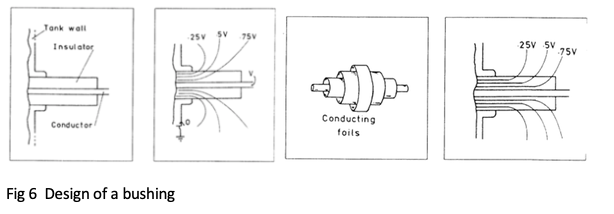
• Bushings
It is sometimes required to take a high voltage conductor through a wall or the tank of a transformer. In such cases a bushing is required to support the high voltage conductor and to provide the necessary insulation in the axial and the radial directions. A porcelain or resin bushing is used for this purpose. In this case the voltage distribution is non-linear in both the axial and radial directions. The voltage gradient is also high close to the high voltage conductor and this could cause discharges in those regions. The use of conducting cylinders inside the bushing results in a more uniform voltage distribution.
- Generator
-
Electric field theory and simple applications to power plant item design
A field can be described as a spatial distribution of a quantity, which may or may not be a function of time. The concept of fields and waves is essential to describe what Michael Faraday called "action at a distance”. For instance, a mechanical force exists between two electrically charged particles. Since no mechanical bond exists between the objects, the concept of electric field is necessary to describe this force. Other examples of fields in nature are: thermal fields, the earth’s magnetic field and electric field.
In high voltage engineering we are particularly interested in electric and magnetic fields.
Electric fields are caused by the voltage difference between electrodes while magnetic fields are caused by currents flowing in conductors.
Electric fields are important in high voltage engineering due to the following effects:
- The most important concepts in HV is strength and stress, the latter is closely related to electric field. The stress of electric insulating materials is adversely affected by excessive electric field magnitudes.
- The presence of electric fields causes induced voltages on non-earthed objects. Similarly, the charge at the base of a thundercloud causes an electric field near the earth surface that may induce charge on objects such as transmission lines. Under dynamic conditions, when the charges vary with time, currents flow in conducting objects.
Magnetic fields do not have a direct effect on the properties of insulating materials but they affect the power system indirectly in the following way:
- High AC currents cause time-varying magnetic fields that induce voltages in conducting loops. Similarly, high time-varying currents due to lightning may cause induced voltages.
These overvoltages cause high electric fields in power system components that may cause failure of the insulation systems.
- Electrostatic Fields
The space around energised high voltage components is occupied by an electric field. The field has the same frequency as the voltage. The magnitude of these fields influences the behaviour of the insulation. It is therefore important to be able to estimate the electric field strength. The following sections provide the definitions and discuss the methods available to analyse uniform and non-uniform fields.
Electric field --- the space surrounding an electric charge or in the presence of a time-varying magnetic field has a property called an electric field. This electric field exerts a force on other electrically charged objects
Electric stress---force, E, on a unit of charge placed in insulant. Charged particles acquire kinetic energy under action of this force.
Voltage --- between two points equals the work done in moving unit charge between them.
Electric stress numerically equals the voltage gradient and can be calculated by E = V/d. Where V is applied voltage and d is the thickness of insulation.
Electric strength --- strength of insulant or maximum stress insulant can withstand.
Insulant can be gases, liquids and solids.
Influencing factors include:
• Pressure
• Temperature
• Voltage waveform
• Electrode material
• Presence of impurities
• Field configuration
Coulombs Law: force between charge r apart
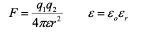
Where εo: permittivity of free space 4πx10-7 F/m
Electric field strength: force at a distance r on unit charge:
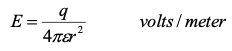
This is the force on ions and electrons within insulating materials.
If the force is high enough, breakdown may occur.
Breakdown voltage of air is 30kV/cm.
Flux density: D = εE Coulombs/meter2
• Consider the boundary between two insulating materials (Fig. 2) having ε1 and ε2
D is continuous at the boundary so
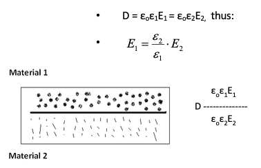
Fig. 2 Boundary between two insulating materials
Example: Imagine a boundary between a solid insulator like polyethylene (εr=2.2 (ε2)) and a gas such as air (εr=1 (ε1)) . Then:
– Stress in air E1 = 2.2x stress in solids
– Significance: weaker insulating material has higher stress
This is the case of gas filled void in solid insulating. It explains why partial discharge may happen in the gas filled void.
- Gauss’s Law
For any closed surface containing a system of charge, the flux out of surface is equal to the charge enclosed:
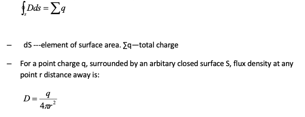
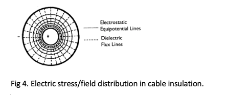
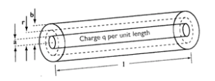
Application of Gauss’s Law --- For a coaxial transmission line such as a cable
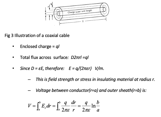
From the equation, it can be easily to obtain the stress distribution of the cable insulation.
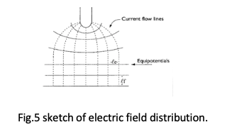
Electric Field Sketching --- experienced engineers can easily plot the electric field distribution in any part of a power plant item,
by following the rules below.
• Current flow lines
– are 90o to the electrodes determined by the force on charged particles.
– spread out on leaving electrodes to decrease current density and thus voltage gradient.
• Equipotentials
– Perpendicular to current flow so that dV between equipotential lines are constant.
Example: A simple bushing and voltage distribution. Stress can be reduced by using concentric metal cylinders.
Computer Solutions --- in modern days, engineers often use computer software packages (such as COMSOL) to obtain electric field distribution for HV design. This may involve the use of finite-element method. Students are recommended to find relevant references to learn more details of the method. - Electrostatic Fields
-
Worked Examples
- Worked Example 1
The inner conductor of a concentric cable has a diameter of 3cm, the outer diameter of the insulation is 8.5cm. The cable is insulated with two materials having a relative permittivity of 5 and 3 respectively, with corresponding safe working stresses of 38kV/cm and 26kV/cm. Calculate the radial thickness of each insulating layer and the design voltage of the cable.
Click here to see solution of Example 1
- Worked Example 2
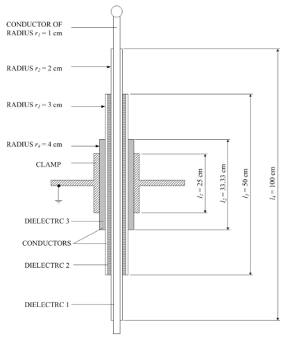
A capacitor bushing with three layers of conductors is designed for field control in a power transformer as data tabulated below.
Internal diameter of the conductor: 20mm
Internal diameter of the earthed flange: 80mm
Internal diameter of the other two layers of copper foils are: 40mm and 60mm respectively.
Length of earthed flange: 100cm
Relative permittivity of the mica insulator: 3.5
(i) Calculate the axial length of the conducting foils to withstand maximum stress in the insulator layer.
(ii) Develop the 66kV capacitor bushing with labelling of relevant dimensions and showing the place of conductive foils used.
(iii) Determine the voltage V1, V2 and V3 across each layer.
(Note: Capacitance between concentric cylinders C= [εr x L]/[18 ln (R/r)] nF)
Click here to see solution of Example 2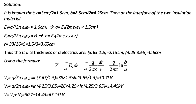
Solution to Worked Example 2:
• Enclosed charge = ql
• Total flux across surface: D2πr1l1= D2πr2l2 = D2πr3l3=…=ql
(i) L1*r1=L2*r2=L3*r3=L4*r4 = 100*1
Therefore, L1 =100/2=50cm, L2 =100/3 = 33.3cm, L3 =100/4=25cm.
(ii)
(iii) Capacitance between concentric cylinders C= [εr x L]/[18 ln (R/r)] nF
C1 = [3.5x0.5]/18 x ln(2/1)] = 140.25 nF
C2 = [3.5x0.33]/[18 x ln(3/2)] = 158.18 nF
C3 = [3.5x0.250/[18 x ln(4/3)] = 169.12 nF
Because: C1V1 = C2V2 = C3V3
V2 = V1 (C1/C2) = V1 (140.25/158.18) =0.89V1
V3 = V1 (C1/C3) = V1 (140.25/169.12) = 0.83V1
Total voltage V1 +V2 +V3 = 66kV/sqrt(3) = 38.1 kV
(V1+0.89V1+0.83V1) = 38.2, V1 = 14.04kV, V2 = 12.50kV, V3 = 11.66kV - Worked Example 1
-
-