-
Lecture 2: Insulating Materials, their Properties and Breakdown Theory
- Learning objectives:
• Introduce the concept of insulation materials, the forms of breakdowns
• Introduce the concepts of insulation properties and provides the properties of selected insulation materials
• Assess the breakdown mechanisms of solids insulation materials
• Demonstrate the concept of partial discharge (PD) and how to numerically analyse the PD activities
• Assess the breakdown mechanism of gases insulation materials
• Appreciate Paschen’s Law and its engineering significance
- Learning objectives:
-
Insulation and insulation materials
An insulating material used in bulk to wrap electrical cables or other equipment is called insulation. In electrical insulation material, internal electric charges do not flow freely; very little electric current will flow through it under the influence of an electric field. This contrasts with other materials, semiconductors and conductors, which conduct electric current more easily. The property that distinguishes an insulator is its resistivity; insulators have higher resistivity than semiconductors or conductors. Where a voltage difference exists between two conductors, it is necessary to apply insulation material or insulator to keep them apart, and to prevent electrical current to flow undesirably from one conductor to the other. In other words, insulators (insulation materials) are used in electrical equipment to support and separate electrical conductors without allowing current through themselves.
The term insulator is also used more specifically to refer to insulating supports used to attach electric power distribution or transmission lines to utility poles and transmission towers. They support the weight of the suspended wires without allowing the current to flow through the tower to ground.
The term “dielectric” is often used in place of insulation. Dielectric (or dielectric material) is an electrical insulator that can be polarized by an applied electric field. This lecture provides the properties and the breakdown theory of various insulation materials, including gases, liquids and solid insulation.
The most commonly used insulating gas is air at atmospheric pressure, as employed on overhead power lines and open air substations. For air, the most important property, in terms of maintenance of equipment and for auto-reclosing systems, is the ability to restore its insulating properties after disconnection of the voltage.
Sulphur hexafluoride (SF6) has been widely used at a higher pressure in compact metal clad gas-insulated substations (GIS). Its distinctive property is that it is electronegative and discharges are suppressed by the de-ionizing action of the gas.
Certain types of liquids, such as insulating oil, can be used as insulating materials, having better insulating properties than gases. Insulating oils, derived from petroleum, is widely used in power plant items such as transformers and switchgears. They often perform in two functions including provision of electrical insulation and help to dissipate heat. Insulating oils are also used as impregnants for paper dielectrics.
Likewise, solid insulating materials are potentially better insulating materials than liquids and gases. Unlike gases, liquid and solid insulating materials are generally not self-restoring. These include paper, mica, and mad made materials such as polyethylene, cross-linked polyethylene (XLPE) etc. -
Forms of breakdown: flashover, sparks and arcs
A perfect insulation does not exist, because even insulations which contain small number of mobile charges (charge carriers) can carry current. In addition, all insulation materials become electrically conductive when a sufficiently large voltage is applied so that the electric field tears electrons away from the atoms, known as insulation breakdown. The voltage causing the breakdown is known as the breakdown voltage of an insulation material.
Discharge is the main breakdown mechanism for the gaseous insulation. When the outermost electron of an atom is given sufficient energy to move completely out of the field of influence of the remainder of the atom, the electron becomes detached and the atom becomes ionised, leading to discharge in gaseous insulation.
The term of flashover is often used to indicate an electric discharge over or around the surface of an insulator. Consider the schematic of a simple power system, shown in Figure 1. The gap shown typically represents the shortest distance from the high voltage wire to ground – often across an insulator. Due to an overvoltage the air in the gap breaks down (flashes over) due to the increased electric field strength. The mechanism of flashover depends on the nature of the gap. The wave shape of the overvoltage also affects the value of the breakdown voltage. Typically the flashover voltages of short duration impulses are higher than for AC and DC.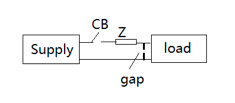
Figure 1 An example of part of a power system with gap
Often the flashover of the gap is initiated by an external overvoltage, such as a lightning surge. Once the gap has flashed over an arc is formed (provided that the impedance Z is not too high), maintained by the system voltage (AC or DC) and a large fault current flows that has to be cleared by the circuit breaker (CB in Fig. 1). If the impedance is high, it may not be possible for a stable arc to form; in such cases intermittent or repetitive sparking may occur. -
Insulation properties
• Loss Tangent tanδ
For a perfect dielectric, the power factor (or power loss) is zero. As long as the material is not a perfect dielectric, the power factor is not zero and it can be represented using the equivalent circuit in Figure 2. The current leads the voltage by an angle of less than 90°, as shown in Figure 2.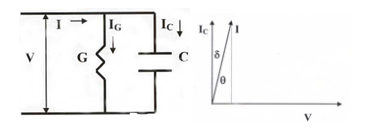
Figure 2 The equivalent and leakage current of insulation in plant items If C is the capacitance of the insulation, say of a cable, and V is the applied voltage, ω=2πf, then
Charging current I = VωC
• All dielectrics have two types of losses
– Conduction loss due to flow of charge through dielectrics
– Dielectric loss due to movement or rotation of atoms or molecules in an alternating field.
• When considering dielectric loss, permittivity ℇ is often considered as a complex number
– ℇ = ℇ’ + jℇ’’ or C = C’+ jC”
• Angle δ is known as the loss angle
– Tan δ = ℇ”/ℇ’ ---loss factor or dissipation factor
– Total loss is expressed as: V2ωC tanδ
The power loss is proportional to V2 and tanδ. The loss tangent tanδ is usually small, but it increase when there is moisture ingress and with aging, so it has been a good indicator of insulation condition.
• Volume resistivity
The resistance between opposite faces of a unit cube of the insulating material, to be measured with direct current. It is a fundamental property that quantifies how strongly a given material opposes the flow of electric current. Although it has no direct bearing on the behaviour of an insulating material under ac conditions but it is a useful indicator of insulation quality.
• Permittivity and Relative permittivity
Permittivity describes the amount of charge needed to generate one unit of electric flux in a particular medium. Accordingly, a charge will yield more electric flux in a medium with low permittivity than in a medium with high permittivity. Permittivity is the measure of a material's ability to store an electric field in the polarization of the medium.
Relative permittivity is the factor by which the electric field between the charges is decreased relative to vacuum. Therefore, relative permittivity of a material is its (absolute) permittivity expressed as a ratio relative to the permittivity of vacuum. Likewise, relative permittivity is the ratio of the capacitance of a capacitor using that material as a dielectric, compared with a similar capacitor that has vacuum as its dielectric. Relative permittivity is also commonly known as dielectric constant.
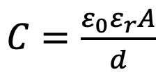
For a parallel plate capacitor, the relative permittivity of the insulating medium determines the capacitance value as given in the equation below. Here, εr and εo are the relative permittivity and permittivity in free space. The table below shows the relative permittivity of a selected list of materials.
C = (εrεoA)/d
Table 1 – Properties of typical insulation materials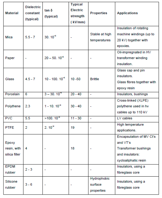
-
Breakdown in solid insulation
Understanding the mechanism of breakdown mechanisms forms the basis for HV plant design, as the many different breakdown mechanisms are fundamental to determining the electric strength of solid insulation. These mechanisms mainly include:
• Thermal breakdown
• Treeing/Tracking
• Chemical and electrochemical breakdown
• Breakdown by internal partial discharge
The electric strength can be as much as 100kV/mm and greater, e.g., some crystalline materials and polymers, the mean value in practical insulating systems rarely exceed 15kV/mm.
• Thermal breakdown
During normal operating condition, plant insulation receives heat from adjacent conductor loss (I2R) and dielectric loss (ωC V2tanδ). The heat raises the temperature of insulation. Thermal runaway happens when the process becomes cumulative, i.e., rising insulation temperature leads to higher losses, and higher losses lead to higher temperature. Thermal conductivity and cooling is therefore important in HV design.
• Treeing/tracking
Tracking is often referred to the electric treeing caused failure in outdoor insulation. In electrical engineering, treeing is an electrical pre-breakdown phenomenon in solid insulation. It is a damaging process due to partial discharges and progresses through the stressed dielectric insulation, in a path resembling the branches of a tree. These partially conducting paths ultimately led to premature breakdown and operational failures.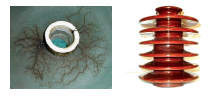
Figure 3 Carbonized electrical trees (or tracking) across the insulation surface(left), an insulator with large creepage distance (right)
In outdoor insulation, design is often dominated by the problems in relation to dirt, pollutants and moisture. The creepage distance, the total distance across the surface of an insulator, has to be extended by special design, such as the shape of an insulator to reduce the electric stress.
In general, electrical treeing first occurs and propagates when a dry dielectric material is subjected to high and divergent electrical field stress over a long period of time. Electrical treeing is observed to originate at points where impurities, gas voids, mechanical defects, or conducting projections cause excessive electrical field stress within small regions of the dielectric. This can ionize gases within voids inside the bulk dielectric, creating small electrical discharges between the walls of the void. An impurity or defect may even result in the partial breakdown of the solid dielectric itself. Ultraviolet light and ozone from these partial discharges (PD) then react with the nearby dielectric, decomposing and further degrading its insulating capability. Gases are often liberated as the dielectric degrades, creating new voids and cracks. These defects further weaken the dielectric strength of the material, enhance the electrical stress, and accelerate the PD process.
• Chemical and electrochemical deterioration
These mechanisms are very much bound up with the thermal mechanism of failure though they are separate processes. The mechanisms are exacerbated by temperature rise, for example for chemical reactions such as oxidation and decomposition in presence of water. Electrochemical deterioration is the result of ionic impurity or possibly from ionisation of the material itself. Ions cause leakage current to flow. On arrival at the electrodes, electrode reactions occur which can produce gas, and insulation and electrodes can be attacked. Failure often results from the incremental process.
• Partial discharge
Partial discharge (PD) is a localized dielectric breakdown (DB) of a small portion of a solid or fluid electrical insulation system under high voltage stress, which does not bridge the space between two conductors. While a corona discharge is usually revealed by a relatively steady glow or brush discharge in air, partial discharges within solid insulation system are not visible.
PD often starts within gas voids, such as voids in solid epoxy insulation. Protracted partial discharge can erode solid insulation and eventually lead to breakdown of insulation.
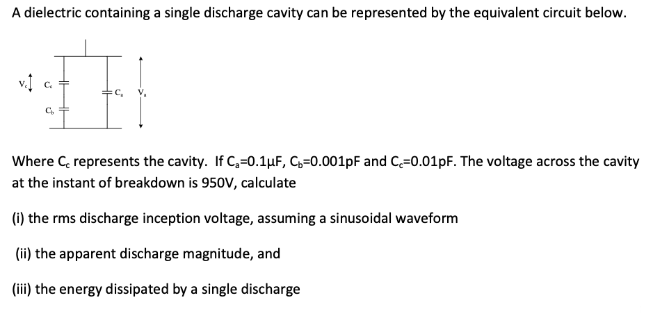
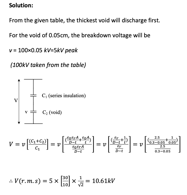
• Discharge inception voltage For a solid insulating material, shown in Figure 4, of relative permittivity εr containing a cylindrical air-filled void of depth t which is small in relation to the thickness D of the dielectric,
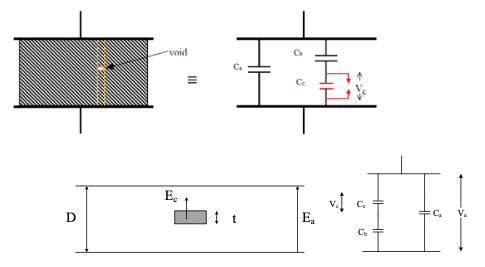
Figure 4 Solid insulation with a void and its equivalent circuit, where Cc represents the capacitance of the void, Cb the capacitance of the sum of insulation material in parallel with the void and Ca the capacitance of all other parts of the insulation.
In the equivalent circuit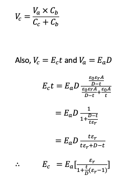
Where, capacitance value can be calculated from:
Eg is the stress of the void and Ed the stress in the solid dielectric. The electric strength of a gas is lower than that of solid insulation. When the applied voltage Va is increased to a certain value known as the discharge inception voltage, so that the peak electric stress in the cavity is equal to the electric strength of the gas in it, an electric discharge occurs in the gas.
When partial discharge occurs, it may appear many times each cycle of power supply, as shown in the pattern given in Figure 5.
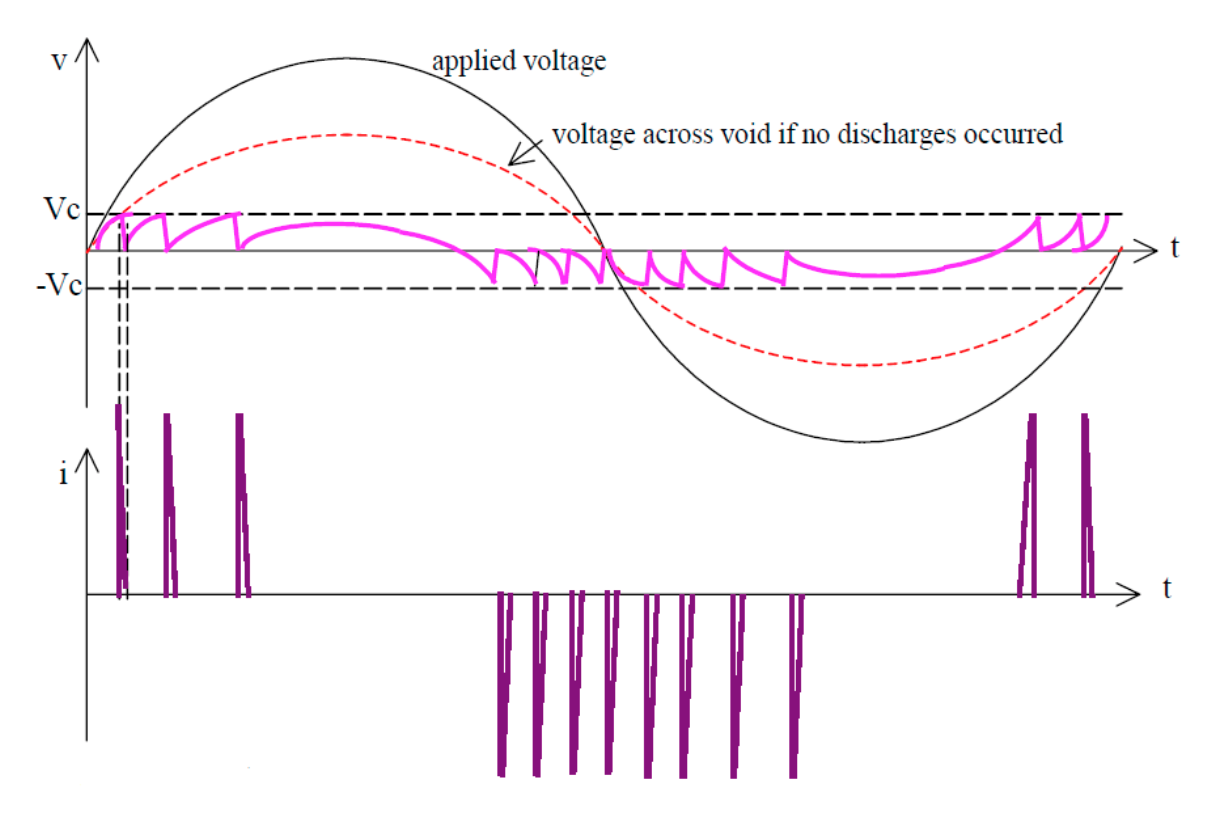
Figure 5 Internal PD pattern over a cycle of power supply, voltage waveforms applied and in a void during PD process (top), and the discharge current pulses (bottom).
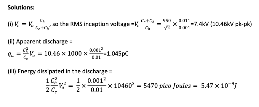
• Energy dissipated in discharge
The energy dissipated in discharge =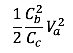
The energy dissipated cannot be determined directly as there is no means of assessing Cb and Cc. However, it is possible to measure the energy dissipation indirectly from the terminals of the sample.
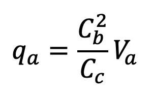
This is the apparent discharge magnitude, also known as discharge magnitude.
-
Breakdown of insulating liquids
Insulating oils, derived from petroleum, is widely used in power plant items such as transformers and switchgears. They often perform in two functions including provision of electrical insulation and help to dissipate heat. Insulating oils are also used as impregnants for paper dielectrics.
Their breakdown mechanisms include:
• Electronic breakdown
- Production of free electrons in the gap by electron emission from the cathode
- Acceleration of electrons by field and loss of energy through collision with liquid or impurity molecules
- Ionisation leading to instability
• Cavitation mechanism – formation of bubbles, the breakdown occurs when local stress exceeds oil insulation strength, caused by one or more of the following
- Gas pockets in electrode surface
- Electrostatic repulsion between space charge overcoming surface tension of liquid
- Gaseous products of ionisation molecules
- Vaporisation of liquid by discharges from irregularity on electrode surface
-
Breakdown in insulating gases
Insulating gases include those used in outdoor power systems, air, consisting mainly of nitrogen and oxygen. Compressed gases, such as SF6, are used in indoor equipment. A gas atom, like any atom, consists of a nucleus, having a positive electric charge and negatively charged electrons in the orbits. Normally, the gas atoms have zero charge as the positive and negative charges cancel out and unlike in the case of conductors of electricity, the electrons are not mobile. However, under certain conditions, notably a high electric field, the gases can become ionized as electrons are freed and cause the flow of electrical current. This is manifested as electrical discharges that develop in the high field regions, leading to sparks (low current discharges) or power arcs (high energy discharges). Lightning is an impressive manifestation of this effect.
• Townsend discharge
Or Townsend avalanche is a gas ionisation process where free electrons are accelerated by an electric field, collide with gas molecules, and consequently free additional electrons. Those electrons are in turn accelerated and free additional electrons. The result is an avalanche multiplication that permits electrical conduction through the gas. The discharge requires a source of free electrons and a significant electric field; without both, the phenomenon does not occur.
The Townsend discharge is named after John Sealy Townsend, who discovered the fundamental ionisation mechanism by his work between 1897 and 1901. As shown in Figure 6, the avalanche effect in gas subject to ionising radiation between two plate electrodes. The original ionisation event liberates one electron, and each subsequent collision liberates a further electron, so two electrons emerge from each collision to sustain the avalanche.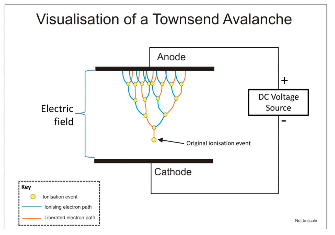
Figure 6 Visualisation of Townsend discharge
• Streamer discharge
Also known as filamentary discharge, is a type of transient electrical discharge. Streamer discharges can form when an insulating medium (for example air) is exposed to a large potential difference. When the electric field created by the applied voltage is sufficiently large, accelerated electrons strike air molecules with enough energy to knock other electrons off them, ionizing them, and the freed electrons go on to strike more molecules in a chain reaction. These electron avalanches (Townsend discharges) create ionized, electrically conductive regions in the air near the electrode creating the electric field. The space charge created by the electron avalanches gives rise to an additional electric field. This field can enhance the growth of new avalanches in a particular direction. Then the ionized region grows quickly in that direction, forming a finger-like discharge called a streamer.
Streamers are transient (exist only for a short time) and filamentary, which makes them different from corona discharges. They are used in applications such as ozone production, air purification or plasma medicine. Streamers pave the way for arcs and lightning leaders, in which the ionized paths created by streamers are heated by large currents. Streamers can also be observed as sprites in the upper atmosphere. Due to the low pressure, sprites are much larger than streamers at ground pressure, see the similarity laws below. Figure 7 shows streamer discharges into the air from the high voltage terminal of a large Tesla coil. The streamers form at the end of a pointed rod projecting from the terminal. The high electric field at the pointed end causes the air to ionize there.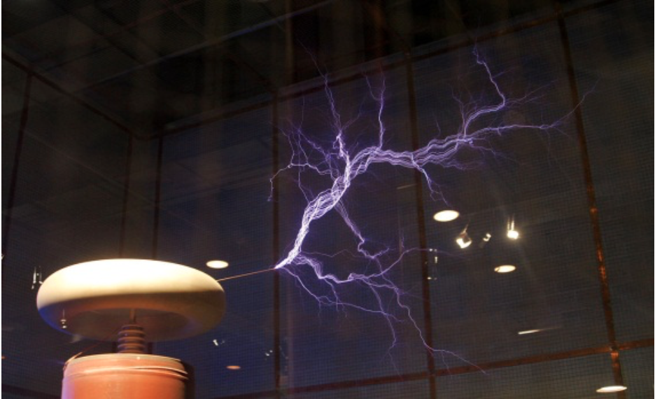
Figure 7 A view of streamer discharge
• Corona discharge
A corona discharge is an electrical discharge caused by the ionization of a fluid such as air surrounding a conductor that is electrically charged. Spontaneous corona discharges occur naturally in high-voltage systems unless care is taken to limit the electric field strength. A corona will occur when the strength of the electric field (potential gradient) around a conductor is high enough to form a conductive region, but not high enough to cause electrical breakdown or arcing to nearby objects. It is often seen as a bluish (or other colour) glow in the air adjacent to pointed metal conductors carrying high voltages, and emits light by the same property as a gas discharge lamp.
In many high voltage applications corona is an unwanted side effect. Corona discharge from high voltage electric power transmission lines constitutes an economically significant waste of energy for utilities. In high voltage equipment like televisions, radio transmitters, X-ray machines and particle accelerators the current leakage caused by coronas can constitute an unwanted load on the circuit. In air, coronas generate gases such as ozone (O3) and nitric oxide (NO), and in turn nitrogen dioxide (NO2), and thus nitric acid (HNO3) if water vapor is present. These gases are corrosive and can degrade and embrittle nearby materials, and are also toxic to people. Corona discharges can often be suppressed by improved insulation, corona rings, and making high voltage electrodes in smooth rounded shapes. However, controlled corona discharges are used in a variety of processes such as air filtration, photocopiers and ozone generators.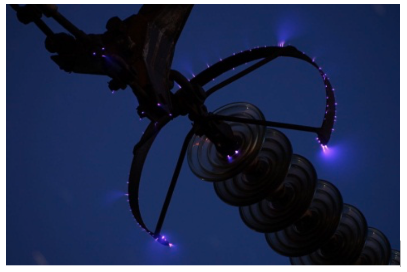
Figure 8 A view of corona discharge
• Paschen's law
It is an equation that gives the breakdown voltage, that is, the voltage necessary to start a discharge or electric arc, between two electrodes in a gas as a function of pressure and gap length. It is named after Friedrich Paschen who discovered it empirically in 1889.
Paschen studied the breakdown voltage of various gases between parallel metal plates as the gas pressure and gap distance were varied:
- With a constant gap length, the voltage necessary to arc across the gap decreased as the pressure was reduced and then increased gradually, exceeding its original value.
- With a constant pressure, the voltage needed to cause an arc reduced as the gap size was reduced but only to a point.
As the gap was reduced further, the voltage required to cause an arc began to rise and again exceeded its original value.
For a given gas, the voltage is a function only of the product of the pressure and gap length. The curve he found of voltage versus the pressure-gap length product (right) is called Paschen's curve. He found an equation that fit these curves, which is now called Paschen's law.
At higher pressures and gap lengths, the breakdown voltage is approximately proportional to the product of pressure and gap length, and the term Paschen's law is sometimes used to refer to this simpler relation. However, this is only roughly true, over a limited range of the curve.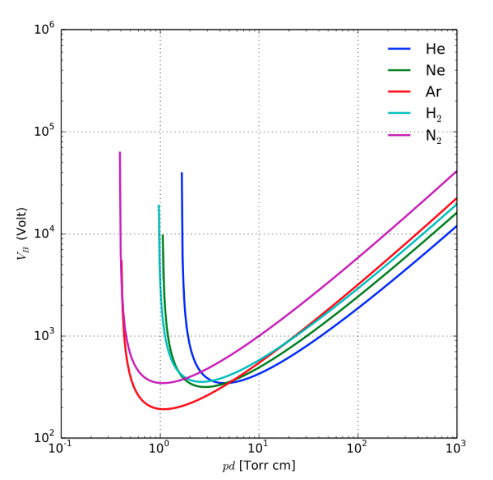
Figure 9 Paschen ( breakdown voltage) curves obtained for helium, neon, argon, hydrogen and nitrogen (Gas Pressure: 1 atm = 760 torr (mmHg) )
In standard conditions at atmospheric pressure, air serves as an excellent insulator, requiring the application of a significant voltage of 3.0 kV/mm before breaking down (e.g., lightning, or sparking across plates of a capacitor, or the electrodes of a spark plug). In a gas, the breakdown voltage can be determined by Paschen's law. The breakdown voltage in a partial vacuum is represented as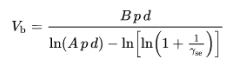
where Vb is the breakdown potential in volts DC, A and B are constants that depend on the surrounding gas, p represents the pressure of the surrounding gas, d represents the distance in centimetres between the electrodes, and ґ se represents the Secondary Electron Emission Coefficient.
Detailed derivation and some background information can be found in the article about Paschen's law. -
Vacuum Breakdown
At gas pressure of about 10-4 torr, in gaps of a few centimetres, electrons will cross the gap without making collisions with gas molecules. Breakdown under these conditions is electrode-dependent and termed vacuum breakdown. Vacuum breakdown mechanisms include:
• Particles exchange hypothesis: self sustaining interchange of elementary particles between electrodes resulting from secondary emission processes.
• Electron beam mechanisms: electrons emitted from microprotrusions on cathode cause localised resistance heating on cathode and anode heating where the beam impinges. Vapour is released, gaseous ionisation and breakdown occurs as a result.
• Clump mechanisms: small pieces of electrode contamination or electrode material may cross the gap in high fields causing local evaporation on electron impact. -
Worked example 1:
A solid insulating material of relative permittivity 2.5 is used in a capacitor between two metal electrodes. The thickness of the insulating sheet is 0.3 cm. Voids are known to occur in the sheet and their sizes are small relative to the insulation. The depth of each void lies in between 0.01 cm and 0.05 cm. The breakdown characteristics of the gas in void (equivalent to Paschen’s curve) is as follows.
Gap length (cm); 0.02 0.03 0.04 0.0 0.06
Electric field at breakdown (kVpk/cm) 125 110 105 100 95
Estimates the 50Hz root mean square inception voltage.
Click here to view solution.
Worked example 2:
Click here to view solution.
-
-