-
Power Plant Insulation Systems
- Learning objectives
• To appreciate the insulation systems as applied to various power plant items,
• To appreciate the stresses, and aging factors of insulation and their design requirements
• To appreciate the mechanisms of degradation of various insulation systems
• To understand the importance of reducing losses in insulation systems
• To demonstrate the nonlinear voltage distribution in insulation systems
• To understand the design and categorisation switchgears and their advantages and disadvantage
• To carry out simplified engineering calculations on insulator design - Learning objectives
-
Rotating machinery
In a rotating machine, the insulating material has to withstand various types of stresses. Some of the stresses are unique to rotating machineries, so the insulating materials used differ from other plant items. The electrical and mechanical characteristics of insulation at temperatures up to 180°C are or vital significance. If it softens at working temperature, or lose too much strength, or ages rapidly, then mechanical and electrical failure can happen. IEC 216 is a guide to the thermal endurance properties of the insulating materials. BS2757 (IEC85) contains details of thermal classification which can be used as a guide to thermal stability at the temperatures listed. Insulating materials can be categorised into the following 7 types:
• Class Y – up to 90˚, unimpregnated paper, cotton, silk, natural rubber etc.
• Class A – up to 105˚, paper, cotton, silk impregnated with oil or varnish.
• Class E – up to 120˚, phenol formaldehyde laminats with cellulosic materials, epoxy resin
• Class B – up to 130˚, inorganic fibrous and flexible materials such as mica, glasses, fibres bonded and impregnated with organic resin.
• Class F – up to 155˚, as class B with approved resins.
• Class H – up to 180˚, as class B, with silicone resin, silicone rubber
• Class C – above 180˚, mica, asbestos, ceramics, glass etc.When designing an rotating machinery, the following considerations are made.
• Properties of materials
• Operating conditions, in particular, temperature and vibration
• CostMain areas of concerns include:
• Main wall insulation thickness
• Stresses at coil corners
• Discharges at where coil the coils leave slot
• Temperature cycling
• Mechanical integrityIn large AC generators, the rotor winding may contain many coils, which in turn consists of many turns, as shown in Figure 1. Insulation consists of inter-turn insulation which is typically resin-bonded glass fabric or mica-tape. Insulation between coils and rotor body is resin-bonded glass-fibre or nomex. Coils are often pre-fabricated and heat consolidated.
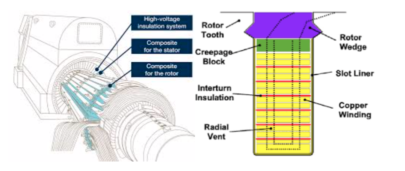
Figure 1 Schematic and cross-section of a rotor winding as seen in an ac generator.
For stator windings shown in Figure 2, each conductor is made of small conductors insulated with glass braid and resin. The main insulation is mica flakes bonded with epoxy resin. It is usually heat and pressure formed and should be void free. An important feature of the stator bar is the corona protection tape which is wound on the outside of the bar for the complete length. It helps to smooth the field distribution and reduce partial discharge activities in the same way as semiconductor layer in cables. End-windings have to be well supported against mechanical forces. Cooling play an important role in extending insulation life.
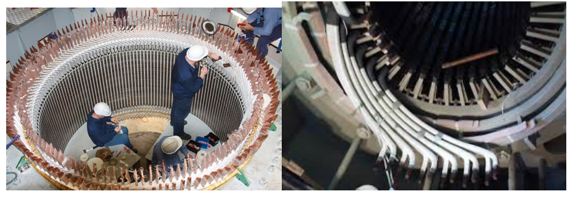
Figure 2 Stator winding and end-winding in a large AC generator
In rotating machines, the following stresses are the factors causing failures and aging.
• Thermal:
– Cumulative thermal degradation resulting in delamination, cracking, embrittlement or depolymerisation
• Electrical:
– Internal discharges causing erosion, transient pulsing from switching surges, tripping on overload
• Mechanical:
– Differential expansion and contraction. Bar vibration
• Environmental:
– Contamination from water, oil, dust, carbon, salt, rust, sand. Radiation degradation.Thermal aging to insulation includes:
• Core insulation
– Burnout at high temperature
• Stator and rotor winding insulation
– Thermal cycling
• Tape separation and girth cracking
– Loosening of endwinding bracing and packing
– Loosening of slot wedges
– Abrasion
• Degradation at continuous high temperatures
– Degradation of conductor stack bond
– Degradation of groundwall bond
– Degradation of slot packing, wedging and endwinding bracing
– Differential expansion between coils and bracing materialsElectrical Aging to Insulation is caused by:
• Core insulation
–– Overheating of ends of core due to underexciting
–– Overheating of back of core due to overexciting
• Stator winding insulation
– Electrical discharges
• Partial discharge
• Discharges at conductor surface
• Internal groundwall discharge
• Discharges at the outer surface ( slot discharges, endwinding discharges
• Surface tracking and moisture absorption
• System surge voltage
• Unbalanced supply voltageMechanical aging factors include:
• Core insulation
– Core fretting, relaxation and failure
• Inadequate core building procedures
• High vibration in service
– Back of core overheating and burning
• Stator winding insulation
– 100Hz bar bounding forces
– Electromagnetic forces in endwindings
– Transient forces
– Abrasive materials
– Centrifugal forcesInsulation may suffer from the following chemical aging factors:
• Water absorption
– Presence of moisture reduce insulation resistance to ground, loosens bonding
• Chemical aging
– Delamination and swelling, organic material worse in deterioration
• Radiation aging -
Transformer
In transformers, metallic casing is always required to house the windings as shown in Figure 3. Oil and paper /pressboard are required. Oil provides insulation between windings and metallic tank, as well as a means of cooling. It is mineral hydro-carbon oil, dried with moisture content less than 15ppm. With excessive amount of moisture, electric strength would be reduced. Oxidation of oil, accelerated at high temperatures, leads to “sludge” formation reducing electric strength and hampering free circulation of oil and moisture content. The paper/pressboard insulation helps to provide mechanical strength and forming paths for oil to flow, helping with cooling.
There are cases where mechanical strength rather electrical is of more importance. In this case, coil clamping, supporting rings and lead support structures may be used. Wood, laminated wood and synthetic resin bonded papers are also used.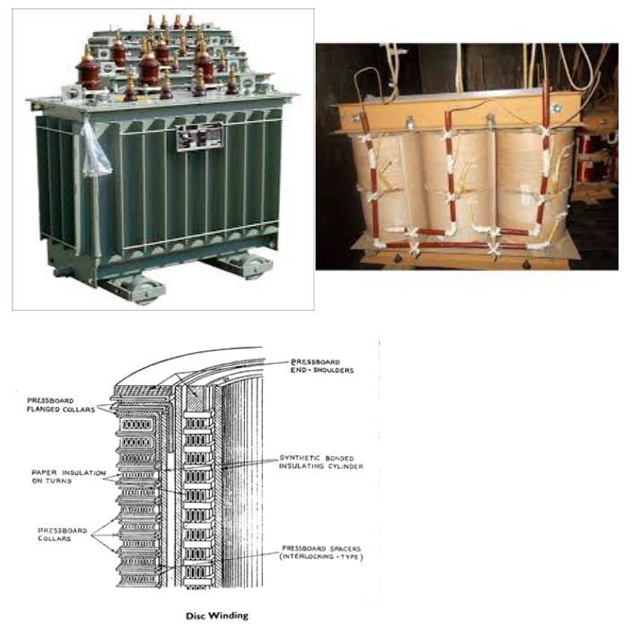
Figure 3 The outside look, windings and the cross sectional view of the windings in a transformer
Transformer insulation has to play a number of roles apart from insulation– Oil cools transformer as well as providing insulation
– Pressboard and plywood have to provide mechanical strength and forming cooling ducts for oil circulation
– Paper provides conductor insulation
– Assembly is complex and design stresses are low in many non-uniform field locations.
– A particular problem is the non-uniform distribution of surge voltage (an example will be given to expand the topic in the section of insulators.
– Without careful control of capacitance to earth, much of the surge voltage would appear in the first few turns of windings, severely stressing the winding insulationIn design of insulation, considerations should be given to electrical stresses. These include:
• Steady state field
– Between H.V. and L.V. windings
– Fields within H.V. windings – layer stress is important
– Field from H.V. windings to core, bushing and tank
• Impulse stress
– Voltage distribution – initially, the distribution is non-uniform.
The HV side windings share more stresses than the ones close to neutral.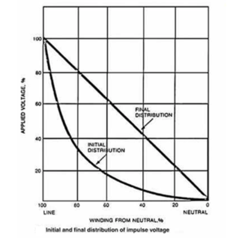
Figure 4 Voltage distribution of impulse voltage in transformer winding
Failure mechanisms of a transformer include:• Insulation degradation
– Insulation material, mainly – cellulose and mineral oil,
– Both deteriorate or decompose under thermal and electrical stress
• Winding failure
– Winding failure -- lightning, overload, or short-circuits. Overload and short-circuits cause extra heat, may cause damage to the winding.
– Lightning or external short-circuits result in mechanical stress on the transformer winding, leading to deformation
For those with tap-changers,
• Tap changers usually have a higher failure rate than transformers, although smaller consequences.
• Improper tap position can cause excessive core loss and consequently excessive heating.
• Contact coking is a major problem.
• Initial deposition of carbon on LTC contacts leads to increased contact resistance, which in turn leads to increased heating and the buildup of carbon.
• Like transformers, LTCs also experience arcing and overheating problems.
• Concentration of fault gases in ‘problem’ LTCs are significantly higher than the levels in a trouble-free unit.
Partial discharge has also been widely researched and reported as a mechanism of transformer failure.
• It may be induced by temporary over-voltage, an incipient weakness in the insulation introduced during manufacturing, or as a result of degradation over the transformer lifetime.
• Different classes of defects result in PD activity in oil filled power transformers. These include: bad contacts, floating components, suspended particles, protrusions, rolling particles, and surface discharges.
• PD is undesirable because of the possible deterioration of insulation with the formation of ionized gas due to this breakdown that may accumulate at or in a critical stress region. This generally involves non-self-restoring insulation that may be subject to permanent damage.
There are some other failure modes, with low probability
– loss of sealing may cause insulation problems and environmental contamination.
– Blocking of pressure relief devices might cause combustible gases to accumulate in the transformer tank and, if unrelieved, lead to an explosion.
– Core vibration can aggravate when core-clamping force is lost, resulting in extra heat and possibly damage of the transformer.
– Heat exchange devices such as radiators, fans and corresponding pumps should work properly to avoid extra heat within the transformer. -
Circuit breakers
Circuit breakers (CB) are categorised by the insulation medium used in their chambers. Common insulation medium (fluid) includes:
• Air at atmospheric pressure
• Compressed air
• Oil (which produces hydrogen for arc extinction)
• Sulphur hexafluoride
• Ultra high vacuumThe insulation medium (fluid) which fills the breakers has a dual function:
• It extinguishes the arc drawn between contacts they open
• It provides insulation between contacts and earth (metallic tank)Figure 5 shows a schematic diagram and the arc extinguishing mechanism of an oil-filled CB.
Two principle arrangements of insulation to earth are provided by the insulating medium in conjunction with solid insulation, as shown in Figure 6.• Live tank: metal tank insulated from ground typically by porcelain insulator
• Dead tank: metal tank at ground potential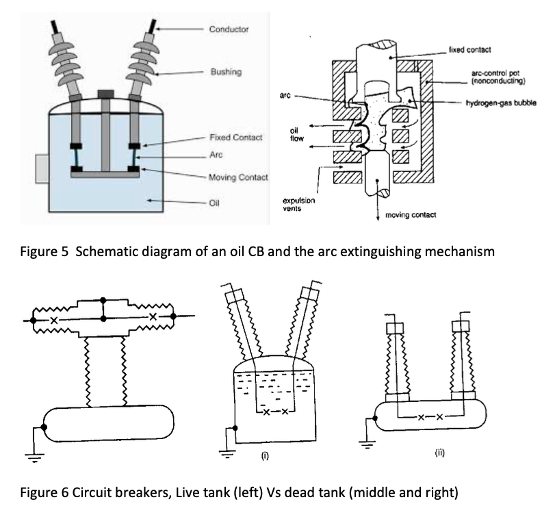
Live tank:
• Construction: up to 12 breaks per phase, 400kV. Three support insulators
• Pollution: sufficient creepage, typically 2.5 to 3.5cms per kV rms.
• Voltage distribution: depends on value of capacitances between contacts and capacitance to earth.
Dead Tank:
Construction: single metal tank at earth potential : use of closed circuit gas system, suitable for expensive SF6, which has the following advantages:• Blast noise minimal
• No exhaust to atmosphere
• Pollution: free from hazards of pollution.
Voltage distribution: grading capacitors across breaks may be required since capacitance to earthed tank is high.
Comparison among various CBs:Air-blast CB (ABCB) advantages:
• Cheapness and availability of interrupting medium and chemical stability.
• High speed operation
• Elimination of fire hazards
• Short and consistent arcing time and therefore, less burning of contacts
• Less maintenance
• Suitable for frequent operation
• Facility for high speed reclosure
The disadvantages are:
• An air compressor plant has to be installed and maintained
• Upon arc interruption, the air blast circuit breaker produces a high level of noise when air is discharged to the open atmosphere
• Current chopping
• Restriking voltage
SF6 CB
• Reliable current interruption, no restriking voltage
• Quiet operation
• The closed gas circuit keeps interior dry, so that there is no moisture problems
• Little erosion because of short arc time
• No carbon deposit
• As the circuit breaker is totally enclosed and sealed from atmosphere, it is particularly suitable for use in coal mines or in any industry where explosion hazard exists.
Vacuum Circuit Breakers (VAB)
• Long life with minimum maintenance
• Completely enclosed and seal construction for indoor and outdoor use
• Extremely short and consistent arcing and total break times
• Suitability for very fast automatic reclosure
• No fire risk
• No noise and no emission of gas or air during operation
Gas-insulated Substation (GIS)
A major development has been the enclosure of all power handling components including busbars, current transformers, voltage transformers, interrupters etc. to form a GIS as shown in Figure 7. SF6 is used as both insulation medium and arc extinguishing medium. This layout has the advantages of:• Reduction in cost and size
• Less susceptible to pollution, humidity, icing etc.
• Can be installed underground.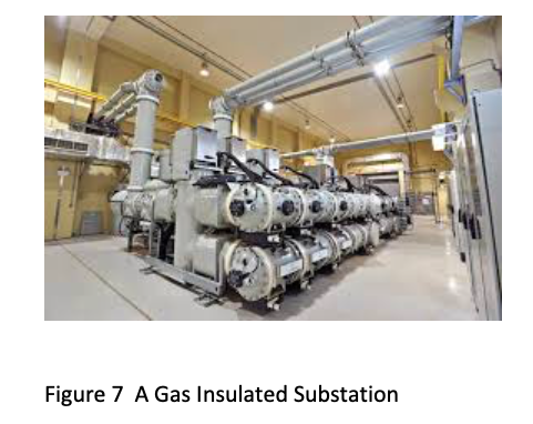
-
Bushing
It is sometimes required to take a high voltage conductor through a wall or the tank of a transformer or CB. In such cases a bushing is required to support the high voltage conductor and to provide the necessary insulation in the axial and the radial directions. Bushing forms an important part in transformer and circuit breakers etc.
• Bushings provide an insulated path for energized conductors to enter grounded electrical power apparatus.
• Bushings are not only exposed to high electrical stress but also may be subjected to high mechanical stress, affiliated with connectors and bus support, as well.
• Its deterioration can have severe consequences. The deterioration mechanisms include a combination of cracking, corrosion, wear and contamination.
• Failure of a bushing can cause flashover, short circuit and thus outage of the transformer, or even catastrophic events such as tank rupture or violent explosion of the bushing and fire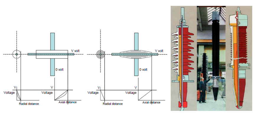
Figure 8 Schematic diagram of straight-through bushing and a capacitance graded bushing (left), Finished graded bushing (right)
-
Cables
Power cables are integral parts of the electrical Transmission and Distribution (T&D) networks. Different types of cable, with a variety of insulation systems, are used for transmitting electrical power at different voltage levels. The proportion of cables in the distribution network in many eastern cosmopolitan cities, including Singapore, Hong Kong and Shanghai, were already 100% in terms of T&D networks.
In early days (before 1990s), paper insulated lead sheath cables (PILC) were dominantly used. Figure 9 shows typical three phase PILC cables. A good proportion of the cables are still in service in UK power networks.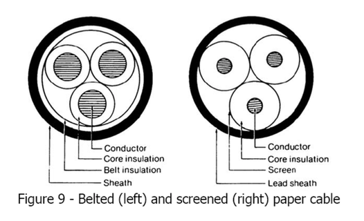
Figure 9 shows a schematic of the cross section of a typical single-core cross-linked polyethylene (XLPE) insulated power cable. This type of cables have largely replaced all previous paper insulated lead sheath (PILC) and ethylene propylene rubber-insulated (EPR) cables in power network.
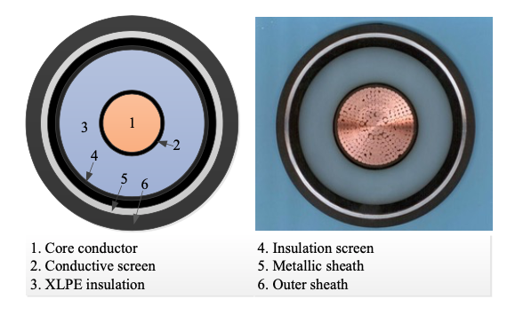
Figure 10: Cross-section of a single-core XLPE power cable, left: Schematic of a cross-section of a single-core XLPE power cable. Right: Image of a cross-section of a single-core XLPE power cable
Cables have two functions in power network,• Conduct heavy current up to rated value
• Maintain continuous working voltage and sustain HV lightning and switching surges
The required dielectric properties:
• High ac and impulse electric strength
• Low permittivity and power factor---low dielectric loss
• Physical and chemical stability
• Good thermal conductivity
• Flexibility for bending
• Inexpensive and readily available
Regarding paper insulation
• The paper used for cable making is a felted mat consisting of long cellulose fibres
• the papers are normally 2-ply but 3-ply is occasionally used at higher voltages.
• The thickness of a single paper is normally between 65 and 190μm but the material density is actually relatively low. That of the fibres is around 1500kgm-3 while that of the finished paper is only around 650 to 1000kgm-3.
• This implies that there is a lot of ‘empty’ space within the fibres and this is generally filled with impregnating compound.
• Impregnated oil• Impart electric strength to the dielectric by excluding air and moisture
• Act as a lubricant to facilitate movement of tapes when cable is bent
• Increase thermal conductivity of dielectric• OIP
• Relative permittivity
• Cellulose fibre: 5.5, OIP: 3.7, Oil: 2.3
• Electric strength of OIP is 50kV/mm to standard short time 50Hz tests and about 200kV/mm when measured with 1/50μs impulse.
• Deign stress varies from 3kV/mm at 11kV to 15kV/mm at 400kV.
• OIP is very gyroscopic, requiring metal sheath and terminations. Former reduces flexibility, both add cost.
In terms of Polyethylene (PE)
• Excellent dielectric property, r = 2.3, tan=0.0003 at 20C. Loss less than 10% of OIP.
• Problem:• contracts on cooling, leading to void formation;
• low melting temperature;
• low discharge resistanceEthylene Propylene Rubber (EPR)
• εr = 3.5, tanδ=0.004, dielectric property not good as PE
• Superior thermal properties and good discharge resistance
Compressed Gas-Insulated Designs
• Applications are short, hundreds metres.
• Usually associated with GIS switchgear and substations
• Compressed GI cables has very low tangent and εr = 1.
• Spacer flashover and particular contamination is the main problem.
For the mostly widely used XLPE insulation:
• It refers to: Cross-linking polythylene
• It can withstand 90 temp, 15 higher than paper cables
• Moisture is dangerous so solid metallic sheath is commonly used as moisture barrier
• Usually thicker than paper insulation, more difficult to handle
• Showing less discharges, particularly with semi-conducting layers
• No need for reservoirs and alarms.
• Applied to most voltages.
• Lower dielectric loss as seen in the table below.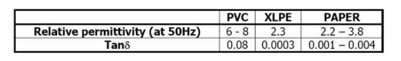
Other components Conductor & Insulation Shields are often required because:
• It refers to: Cross-linking polythylene
• It can withstand 90 temp, 15 higher than paper cables
• Moisture is dangerous so solid metallic sheath is commonly used as moisture barrier
• Usually thicker than paper insulation, more difficult to handle
• Showing less discharges, particularly with semi-conducting layers
• No need for reservoirs and alarms.
• Applied to most voltages.
• Lower dielectric loss as seen in the table below. -
Overhead line and insulator
Overhead lines are used whenever possible due to their economic advantage. The major part of the insulation is provided by air. Overhead lines need mechanical support to provide sufficient height against ground. Towers for support of the lines are made of wood (as-grown or laminated), steel or aluminium (either lattice structures or tubular poles), concrete, and occasionally reinforced plastics. The bare wire conductors on the line are generally made of aluminium (either plain or reinforced with steel, or composite materials such as carbon and glass fibre), though some copper wires are used in medium-voltage distribution and low-voltage connections to customer premises. A major goal of overhead power line design is to maintain adequate clearance between energized conductors and the ground so as to prevent dangerous contact with the line, and to provide reliable support for the conductors, resilience to storms, ice loads, earthquakes and other potential damage causes.
Insulators must support the conductors and withstand both the normal operating voltage and surges due to switching and lightning. Insulators are broadly classified as either pin-type, which support the conductor above the structure, or suspension type, where the conductor hangs below the structure. The invention of the strain insulator was a critical factor in allowing higher voltages to be used.
Insulators are usually made of wet-process porcelain or toughened glass, with increasing use of glass-reinforced polymer insulators. However, with rising voltage levels, polymer insulators (silicone rubber based) are seeing increasing usage.
Suspension insulators are made of multiple units, with the number of unit insulator disks increasing at higher voltages. The number of disks is chosen based on line voltage, lightning withstand requirement, altitude, and environmental factors such as fog, pollution, or salt spray. In cases where these conditions are suboptimal, longer insulators must be used. Longer insulators with longer creepage distance for leakage current, are required in these cases. Strain insulators must be strong enough mechanically to support the full weight of the span of conductor, as well as loads due to ice accumulation, and wind.
Porcelain insulators may have a semi-conductive glaze finish, so that a small current (a few milliamperes) passes through the insulator. This warms the surface slightly and reduces the effect of fog and dirt accumulation. The semiconducting glaze also ensures a more even distribution of voltage along the length of the chain of insulator units.
Polymer insulators by nature have hydrophobic characteristics providing for improved wet performance. Also, studies have shown that the specific creepage distance required in polymer insulators is much lower than that required in porcelain or glass. Additionally, the mass of polymer insulators (especially in higher voltages) is approximately 50% to 30% less than that of a comparative porcelain or glass string. Better pollution and wet performance is leading to the increased use of such insulators.
Insulators for very high voltages, exceeding 200 kV, may have grading rings installed at their terminals. This improves the electric field distribution around the insulator and makes it more resistant to flash-over during voltage surges.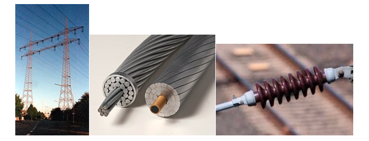
Figure 11 Illustration of overhead line, bundled conductor (Conventional ACSR (left) and modern carbon core (right) conductors), and insulator.
Insulator is an important unit is overhead line system design. It needs to
• Have adequate size and shape to withstand the maximum working voltages and specified over-voltages
• Perform under conditions of pollution
• Withstand high mechanical loadings
• Not give rise to high RFI due to corona.
The suspension insulator separates the line conductors and supports them electrically. It consists the number of porcelain insulator units connected with each other by metal links to form a flexible string. The conductor is connected at the bottom of the string. With the strain insulators, in contrast, the insulator string is in the direction of transmission lines.
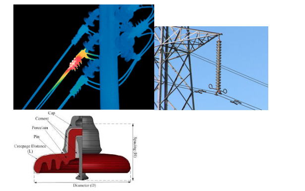
Figure 12 The strain insulator, the suspension insulator string, and the popular cap-and-pin type insulator
Advantages of Suspension Type Insulator
The suspension type insulator has the following advantages.• Each unit operates the voltage of about 11kV and hence depending upon the voltage the appropriate number of discs are connected in series with the string.
• If one of the units is damaged, then it is replaced by the new one and hence no need of replacing the whole string.
• The string is free to swing in any direction and, therefore, great flexibility is provided to the transmission line.
• The conductors are placed below the suspension insulators and hence it partly protects the conductor from lightning.Further on Cap and Pin insulators
• A single unit support 11kV
• Electrical properties for 400kV systemsImpulse withstand volt: 1425kV
Corona extinction volt: 320kV
50Hz withstand volt: 800kV (dry) and 630kV (wet)
For suspension type (vertical)Number of units: 24; String length 4.11m;
Min creepage distance: 12.7m; arc gap: 2.54m.
It is important that the Breakdown Voltage is considered during the design stage.
– Proportional to the distance between HV conductor and ground for both 50Hz a.c. and surge voltage.
– Determines the “dry arcing distance” ---around the total insulator string length. The distance must be sufficient to support volts considerably higher than line volts.
– Size of insulator is determined by the creepage distance required to prevent tracking failure.
Pollution flashover often occurs and must be considered. The process of the flashover is:
• arrival of nearly pure water at an insulator which carries a burden of pollution comprising soluble ionic;
• deposition of droplets from industrial fogs;
• build-up of frost, freezing fog or ice on the fouled surface of the insulator, the ionic components of the fouling then proceeding to depress the freezing point of the water and allow solution at the interface;
• switching in of a circuit containing wet, polluted insulators;
• Arrival of a lighting surge.
Means of remedy for Flashover include:
• Optimised insulator shapes and creepage
– Increase creepage path length without spoiling surface aerodynamics of insulator, inclination from the vertical, insulator profile to maintain air speed.
• Insulator washing (online and offline) (jets or spray) reduce the surface resident layer, Jet washing effective at moving solid pollution, costly high maintenance burden, could cause heavy wetting flashover on some types of insulator, high faults rate on washing equipment.
• Booster shed is a discharge resistant polymer fitted around existing insulator, increase surface creepage length, increases in tolerable pre-wetting is usually four fold, reduces water shedding
• Surface treatment
Simplified calculations can be made in the design of insulator strings. Although the insulators in a string are identical the voltage distribution across the individual units is non-uniform.
-
Worked example:
(i) A 33kV overhead line string insulator can be described electrically as shown in Figure below. A string of 5 insulator units each possessing a capacitance C is used to suspend a transmission line. The air capacitance between each of the unit cap/pin junctions to the earthed tower is 0.1C. Given that the wet surge flashover voltage is 70kV (peak) for each unit, determine whether any individual unit would flash over when the whole unit is subjected to a surge of 250kV (peak) on a rainy day.
(ii) With the design shown, the string efficiency is low due to non-uniform distribution of voltage. Provide one measure, with the aid of a sketch, that can help improve the string efficiency and explain how the improvement is achieved.
Click to view the solution
Solution
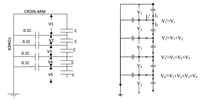
(i) From Kirchhoff’s Law:
I2 = I1 + I1’, therefore, 2πfCV2=2πf0.1CV1+2πfCV1; V2=1.1V1
Similarly:
V3=V2+0.1 (V1+V2)=1.1V2+0.1V1
Substituting V2 for V1
V3=1.31V1
Similarly:
V4=V3+0.1 (V1+V2+V3) = 1.651V1
And V5 =V4+0.1 (V1+V2+V3+V4) = 2.1571V1
V1+V2+V3+V4+V5 =V1+ (1.1V1) + (1.31V1) + (1.651V1) + (2.1571V1) = 250kV.
Therefore, V1 = 33.64 kV
V2 = 38.10 kV, V3 = 45.37kV, V4 = 57.18kV, V5 = 74.71kV
Therefore, the unit at the bottom will flashover.
(ii) At a working voltage of 33kV,
V1 + V2 + V3 + V4 + V5 = 33kV/1.732 = 19.050kV.
V1=2.64kV, V2=2.90kV, V3=3.46kV, V4=4.36kV, V5=5.69kV
String efficiency =Vtotal/(5xV5) = 19050/(5x5690) = 0.670
Significance: -- low string efficiency means that the withstand voltage of the insulator string is low with the same number of units, and the ones close to high voltage end can be more easily broken down.
The reason for the low efficiency is the non-linearity in voltage distribution among insulator units, resulted from the capacitance between the units and line towers. This can be seen from the solution procedures above. With the stray capacitances, the efficiency would be unity.
One solution using a Guard-ring is as shown below.
V4+0.1(V4+V5)=V3+0.1(V1+V2+V3)
and
V5+0.2V5=V4+0.1(V1+V2+V3+V4);
Therefore, V5=1.532V1, V4=1.364V1
V1 + V2 + V3 + V4 + V5 = 33kV/1.732 = 19.050kV, V5=4.63kV
String efficiency =Vtotal/(5xV5) = 19050/(5x4630) = 0.823