-
Overvoltages and Insulation Coordination
- Learning objectives • To understand the concepts and objectives of insulation coordination
• To understand the sources, causes and control measures, of overvoltages, including overvoltage, switching surge and lightning impulse
• To understand the protection afforded by rod gaps and surge diverters
• To understand the propagation of lightning impulses along transmission lines.
• To carry out numerical analysis and to implement designs of the techniques of insulation coordination - Learning objectives • To understand the concepts and objectives of insulation coordination
-
Concepts in insulation coordination
Insulation requirements are essential in HV system and equipment design. In power system operation, the insulation has to with stand:
• Continuous system working voltages
• Overvoltages due to switching and lightning. These overvoltages always have much higher magnitude than working voltage and vary rapidly with time.
Over the years, many concepts and industrial standards have been developed to help design engineers to ensure the HV system design can work safely and reliably in the intended power systems. Some of these are:
Overvoltages: in normal power system operations, voltage is not normally more than 10% of the rated values. Voltages in excess of this level are known as overvoltages. Overvoltages may include temporary overvoltages, switching impulse and lightning impulse over voltages. Typically, their peak magnitude and shape of waveforms are given in Table 1 below.
Table 1: Overvoltages and their manifestations
Withstand voltage: the withstand voltage is the voltage level equipment should withstand for a given length of time or number of voltage applications without failure of insulation.
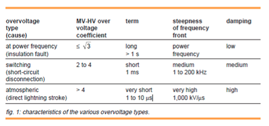
Insulation Flashover and Puncture: When the discharge of current is external-across insulator for example, this is known as flashover. If the discharge current flows through the insulation, it is known as insulation puncture. Normally tests are performed to determine the flashover voltage. This can be seen from Figure 1 below. It is preferred in HV design that the flashover voltage is lower than that is required for the insulation to puncture.
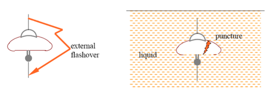
Figure 1: overvoltage or the increased electric field strength causing the air in the gap (often associated with insulator) to break down (flashes over) - vs.- puncture in solid insulation
Basic Insulation Level (BIL): The lightning impulse voltage level the equipment insulation is required to withstand. When lightning impulse over voltage appears in the system, it is discharged through surge protecting devices before the equipment of the system gets damaged. Hence, the insulation of such equipment must be designed to withstand a certain minimum voltage before the lightning impulse over voltage gets discharged through surge protecting devices. Therefore, operating voltage level of surge protecting devices must be lower than the said minimum voltage withstanding level of the equipment. This minimum voltage rating is defined as BIL of equipment.
Insulation coordination: a set of quantitative procedure to achieve the best possible tech-economic compromise for protection of persons and equipment against overvoltages. The considerations include:
- cost of insulation; cost of protective devices; cost of failures Insulation coordination is based on the knowledge of:
Insulation coordination is based on the knowledge of:
• Quantitative description of the magnitude and frequency of the stresses to which components will be subjected.
• Knowledge of insulation strength of components in the form of probability of failure at a particular stress
• Information to decide whether these stresses may be usefully limited by inclusion of protective devices.
Clearance --- the shortest path between two conductive parts.
Creepage distance --- the shortest path between two conductors, but following the outer surface of a solid insulator.
-
Overvoltages
3.1 Lightning impulse
Lightning is a result of storm, a natural phenomenon. Lightning results in surges in electrical power systems. Such surges arise from lightning strikes to or near overhead conductors. These may be classified as:• Direct strokes: when a thundercloud directly discharges onto a transmission line tower or lines. This is the most severe condition but it rare.
• Induced strokes: When the thunderstorm generates negative charges at the base of cloud, objects such as transmission lines and towers develop induced positive charge. As a result, the line is left with huge concentration of charge which cannot leak suddenly. This is how the overvoltage surges result from indirect strokes.
• Back-flashover: if a direct strike to a tower occurs, the tower has to carry large impulse currents. If the tower footing resistance is considerable then the potential of the tower rises. This can cause insulators to back-flashover.(see worked example 1)According to IEC71, lightning surge can be simulated by an a periodical waveform with a front duration of the order of one of µs and a tail duration of tens of µs, as shown in Figure 2 below..
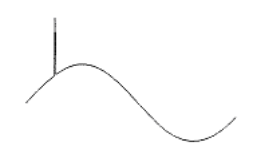
Figure 2 The waveform of a typical lightning impulse
3.2 Switching surges
Sudden changes in electrical network structure give rise to transient phenomena frequently resulting in the creation of an overvoltage or of a high frequency wave train of aperiodic or oscillating type with rapid damping. When the arc between circuit breaker contacts breaks, the full system voltage suddenly appears across the open gap and hence across the circuit (consisting of R, L, and C) making up the system. The resulting voltage consists of a high frequency component superimposed onto the normal voltage. The total is known as restriking voltage and constitutes a switching surge.
According to IEC71, switching surge can be simulated by a periodical waveform with front duration of hundreds of µs and a tail duration of thousands of µs. A typical waveform switching surge is shown in Figure 3.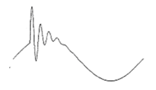
Figure 3 The waveform of a typical switching surge
Origin of switching surges may include any of the following:
• De-energisation of transmission lines, cables. (due to capacitive current chopping)
• Disconnection of unloaded transformers (inductive current chopping)
• Energisation or reclosing of lines and reactive loads
• Short circuits and fault clearance
• Resonance effect
Overvoltage magnitude depend on:
o transmission line length,
o line impedance,
o the degree and location of compensation,
o the circuit breaker characteristics,
o the feeder source configuration and
o the existence of remnant charge from prior energisation of the line.
As the above determines insulation level, reduction of the magnitude of overvoltage is important. Techniques are:
– Resistor insertion
– Closing of circuit breakers at close to voltage zeros.
– The combination of the above.
3.3 Propagation of surge
Long transmission lines are considered to be electrical networks with distributed elements as shown in Figure 4 below..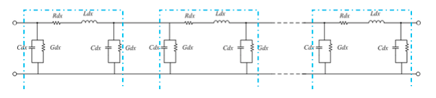
Figure 4 Equivalent circuit of long transmission lines.
For lossless lines, where R=0, and G reaches infinity, a surge would travel at a velocity of

The characteristic impedance of the wave is,

which is in hundreds of ohms for overhead lines, and thousands of ohms for transformer.
At the impedance discontinuities, e.g. a surge arrives at a transformer of Z2 from an overhead line of Z1, then only part of the energy goes through and part of it gets reflected. The following equations are often used for engineering calculations:
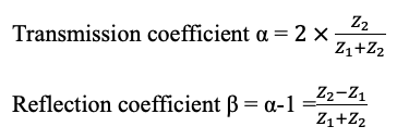
The example in worked example 1 may better help understand the surge propagation and reflection in power systems. The phenomenon of reflection has significant implications in HV system design, as can be seen from other worked examples in the end of the notes.
3.4 Temporary overvoltages
Temporary overvoltage may result from the following: Earth fault, Load sheding, Line energisation, ferro-resonance. For details, one can refer to the reading material: overvoltages and insulation coordination in MV and HV. The link is:
http://www.studiecd.dk/cahiers_techniques/Overvoltages_and_insulation_coordination_in_MV_and_HV.pdf -
Insulation Coordination
This involves the application of a set of quantitative procedure to achieve the best possible tech-economic compromise for protection of persons and equipment against overvoltages. It may involve the following steps:
• Check operating voltage under normal conditions
• Characteristics of the system
• Calculation of temporary overvoltage
• Calculation of switching overvoltage/ (design gaps and arrestors)
• Calculation of lightning overvoltage/Lightning overvoltage characteristics
• Insulation design as regards operating voltage and temporary overvoltage
• Selection of rated impulse withstand voltage of apparatus / introduction of means for reducing lightning voltage, e.g.Line insulation level, earth wire, gaps
• Selection of lightning withstand impulse voltage of apparatusFigure 5 below demonstrates how traditionally how insulation coordination was done.
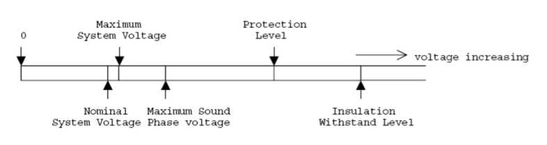
Figure 5 Traditional approach of insulation coordination
More recently, a risk based approach has been applied to insulation coordination. This involves examining the probability density of impulse distributions and the probability of insulation breakdowns as shown in Figure 5.
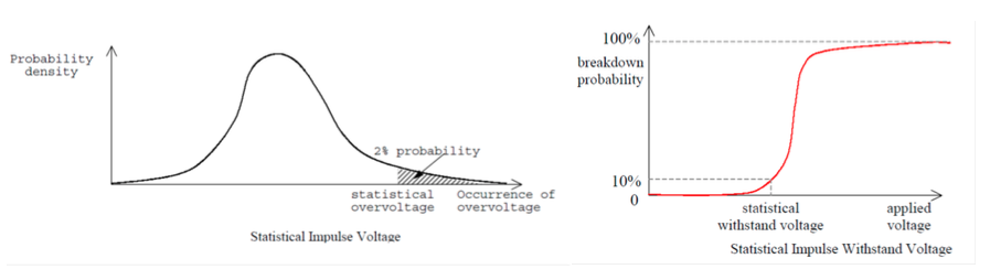
Figure 5 Probability density of impulse distributions and the probability of insulation breakdowns
Then insulation coordination is arranged in a way where the 2% overvoltage probability coincides with the 90% insulation withstand probability. Clearly, by doing this way means there is a risk of failure. However, the risk should outweigh the cost of extra insulation requirement. And the risk can be determined as:
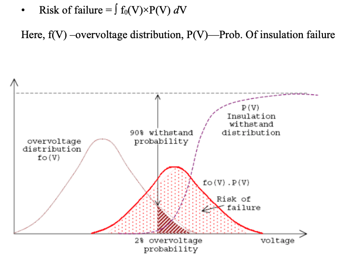
Figure 6 Probabilistic approach to insulation coordination.
Further procedures coverage and procedures on insulation coordination can be found from the link.
http://www.studiecd.dk/cahiers_techniques/Overvoltages_and_insulation_coordination_in_MV_and_HV.pdf -
Overvoltage Protective Devices
-
Worked Examples
Example 1:
A 3-phase 132kV line having BIL of 400kV is supported on steel towers and protected by a circuit breaker. The ground resistance at each tower is 20Ω whereas the neutral of the lines is solidly grounded at the transformer just ahead of CB. During an electric storm, one of the towers is hit by lightning stroke of 30kA.
(i) Calculate the voltage across each insulator string under normal conditions.
(ii) Describe the sequence of events during and after the lightning stroke.
(iii) State and explain ONE measure which can help to avoid any possible flashover/line outage under the circumstance.
Click here for solution to Example 1
Example 2:
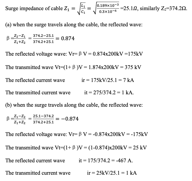
An underground cable of inductance 0.189mH/km and of capacitance 0.3μF/km is connected to an overhead line having an inductance of 1.26mH/km and capacitance 0.009μF/km. Calculate the transmitted and reflected voltage and current waves at the junction if a surge of 200kV travels to the junction,
(a) along the cable, and
(b) along the overhead line
Click here for solution to Example 2
Worked example 3: Separation limit for lightning arrestors
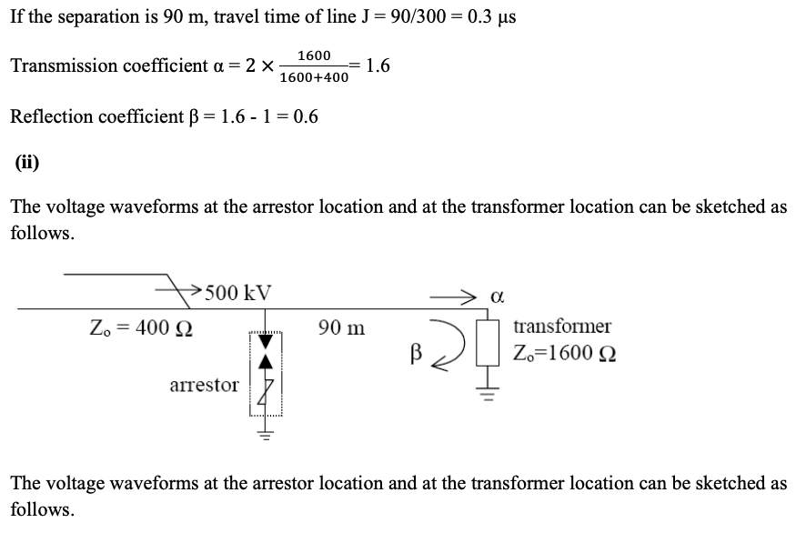
A lightning arrestor having a flashover voltage of 650 kV is located on a main 132-kV busbar providing protection to a 132/33kV transformer having a surge impedance of 1600Ω. The arrestor is subject to a surge of 500kV rising at 1000kV/μs originating on a 132-kV line, of surge impedance 400Ω, connected to the transformer via a busbar. The transformer is effectively earthed.
(i) Assuming the arrestor is 90 meters away from the transformer, determine the time required to travel between the two plant items, transmission and reflection coefficient for the lightning impulse.
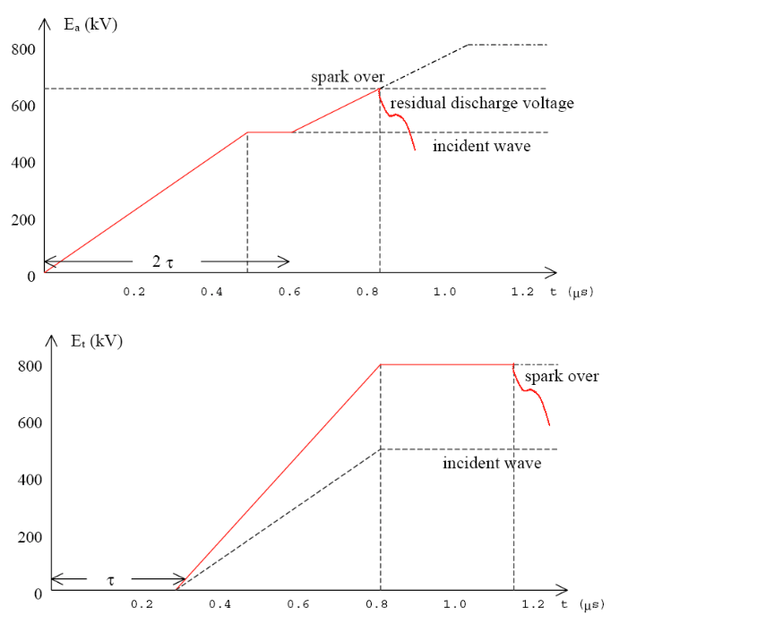
(ii) Sketch the voltage waveform at the location of arrestor and the location of transformer.
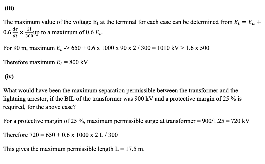
(iii) The lightning impulse insulation level of the transformer on the 132kV side is 900kV. Determine, stating any assumptions made, the maximum possible voltage at the transformer terminal.
(iv) What would have been the maximum separation permissible between the transformer and the lightning arrestor, if the BIL of the transformer was 900 kV and a protective margin of 25 % is required, for the above case?
[ Note: Et =Ea + β(de/dt)x2l /300 ]
Click here for solution to Example 3
A transformer has an impulse insulation level of 850kV and is to be operated with a margin of 15% under lightning impulse conditions. The transformer has a surge impedance of 1600Ω and is connected to a transmission line having a surge impedance of 360Ω. A short length of overhead earth wire is to be used for shielding the line near transformer from direct strikes. Beyond the shielded length, direct strokes on the phase conductor can give rise to voltage waves of the form 820e-0.05t kV (where t is expressed in μs).
If the corona distortion in the line is represented by the expression , where B=120m/μs and eo=180kV, determine the minimum length of shielding wire necessary in order that the transformer insulation will not fail due to lightning surges.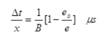
Click here for solution to Example 4
Solutions Example 1
(i) Under normal conditions, the line to neutral voltage is 132kV/sqrt(3) = 76.21 kV. This is below the BIL, so current flowing to earth is zero. Peak voltage across insulator string is 76.2 x sqrt(2) = 107.76kV
(ii) When a lightning strikes, the voltage on earth resistance jumps to 20Ω x 30 kA =600 kV. This exceeds the BIL, and causes flashover, short-circuiting all three phase line to steel arm.
The line voltage will then feed sustained S-C current, until circuit breakers clear the lines.
(iii) One measure is to reduce the earth resistance to 10Ω. Then during a lightning strike, voltage across the earth voltage will be 300kV, which is below the BIL. No S-C occurs.Solution Example 2:
Solution Example 3:
Solution Example 4:
The maximum permissible voltage is 850kV x (100-15)%=850 x 0.85 =722.5kV
The transmission coefficient is 2x1600/(1600+360) = 1.63
Thus the maximum surge voltage allowed is 722.5/1.63= 443.25kV.
This means that the distortion along the lines must reduce the voltage to 443.25kV.
Therefore, 820e-0.05t = 443.25 kV. This gives the delay time as t = 12.3 μs
Substituting into equation,
we have, B=120m/μs, e0=180kV, e = 443.25kV, Δt=12.3μs,
solving the equation gives x =2485m. So the minimum length of shielding wire should be 2485m.
Any lightning impulse within the distance, if not arrested, will cause danger of flashover or breakdown.