-
Dr Azmy Gowaid
School of Computing, Engineering and Built Environment
Glasgow Caledonian University
Email: azmy.gowaid@gcal.ac.uk
Indicative reading
Salameh, Z. (2014). Renewable energy system design. Waltham,
Massachusetts: Academic Press. (Available online)
Chapter 3 up to section 3.5.4
Fox, B., Flynn, D., Jenkins, N., Milborrow, D., Bryans, L., Anaya-Lara, O.,
O’Malley, M., et al. (2014). Wind power integration : connection and system operational aspects. (Second edition) (Available online)
Chapter 3 sections 3.1, 3.2, 3.3 , 3.4.1 -
Wind Resources
European Wind Atlas
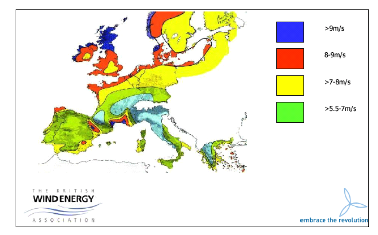
Scotland enjoys high wind energy resource.
Wind Speed DistributionWeibull and Rayleigh Probability Distributions
It was found by measurements that wind speed at a certain site over one year follow a Weibull or Rayleigh probability distribution.
It implies that moderate wind speed range has highest probability w. r. t. low or high speed wind.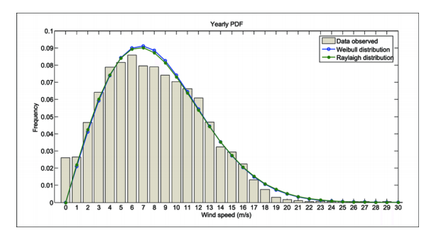
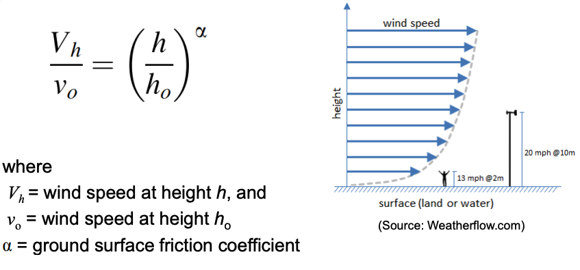
Wind Speed vs Height
Effect of tower height from ground on wind speed
The wind sheer at ground surface causes wind speed increase with height in accordance with:
-
Vertical vs. Horizontal Axis Wind Turbines
Vertical Axis Wind Turbine (VAWT)
Darrieus VAWT
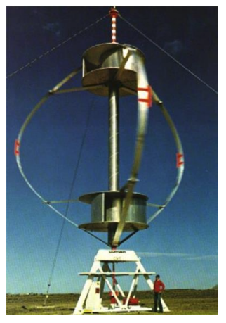
Image by Salameh, Z. “Renewable energy System Design”, chapter 3
- Design patented 1931.
- The only VAWT manufactured commercially at a wide scale.
- Used for low power application.
- Gearbox located on the ground
- No tower needed for support
- No need for yawing mechanism to turn the rotor against the wind.
- Low efficiency and not self starting
- Requires guy wires for support.
Vertical Axis Wind Turbine
Other types of VAWTs
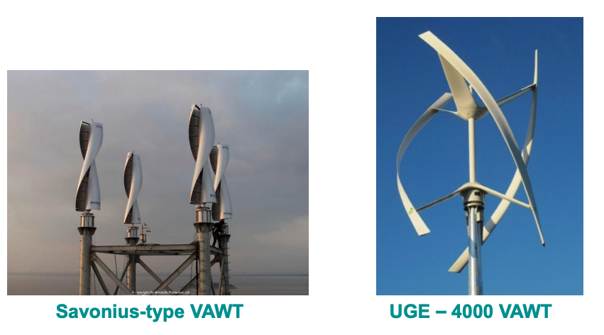
Image by Salameh, Z. “Renewable energy System Design”, chapter 3
Vertical Axis Wind Turbine
Cross-flow VAWT
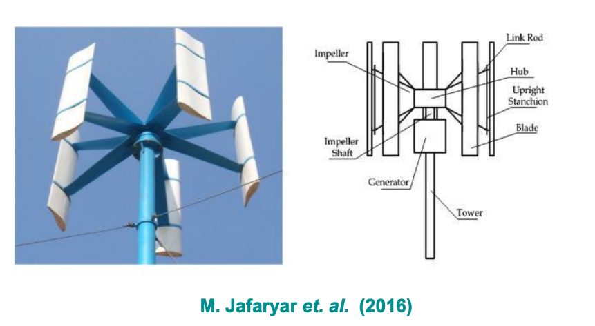
Vertical Axis Wind Turbine
Advantages:
• Generator and gearbox nearer to the ground and easier to maintain
• No need for tower support (less cost)
• No need for yawing mechanism to turn the rotor against the wind
Disadvantages:
• Less efficient that HAWTs (closer to ground, lower wind speed).
• More difficult control and starting.
• May need support through guy wires
• Uneven distribution of mechanical stress to blades.
• Therefore, not suitable for high power (utility scale)
Horizontal Axis Wind Turbine (HAWT)
Advantages:
• Easier to control and start w.r.t. VAWTs
• Higher efficiency
• Easier to design for high power ratings at commercial scale.
Disadvantages:
• Need for strong tower to support the nacelle and blades
• Generator and gearbox are up in the nacelle
• Yawing mechanism needed
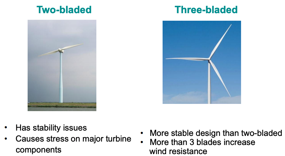
Types of HAWT (blades count)
Types of HAWT (upwind/downwind)
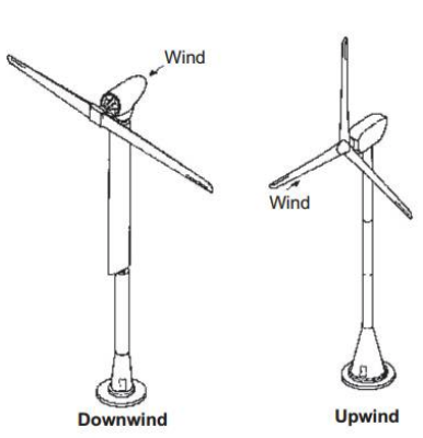
Image by Salameh, Z. “Renewable energy System Design”, chapter 3
- Upwind WT has the rotor facing the wind; this is the more popular design.
- Upwind WT avoids the wind shade of the tower.
- Upwind WT needs a yaw mechanism to keep the rotor facing the wind.
- Downwind WT has the wind hitting the turbine first
- The nacelle may be designed to follow wind direction without a yaw mechanism.
- Downwind is not a suitable design for large turbines.
Types of HAWT (Fixed speed WT)
- The early wind turbine designs were fixed speed
- Traditionally known as the “Danish concept” pioneered by the Danish manufacturer “Vestas”
- Blades rotate at a fixed speed
- In some models two generators with different number of poles are used to allow operation at two different speeds.
- Fixed speed WTs have lower energy harvest than variable-speed WTs
- Mostly limited to small and medium sized wind turbines (<600kW)
Types of HAWT (Variable speed WT)
- Multi-megawatt WTs are normally variable speed WTs
- Variation of blades rotation speed captures more wind energy.
- Vestas was first to introduce limited variable speed operation with OptiSlip™ technology
- Variable speed wind technology requires power converters and more complex control systems
- Variable speed WTs are the current WT technology standard.
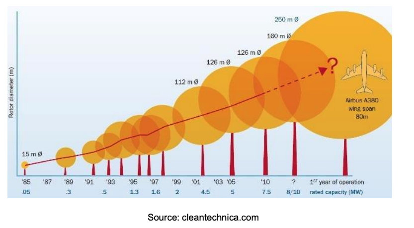
WT Power ratings
Consortium of industry organizations, research institutes, universities, and governmental agencies are working to overcome technical challenges of designing 10-20 MW wind turbines.
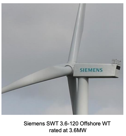
WT Power ratings
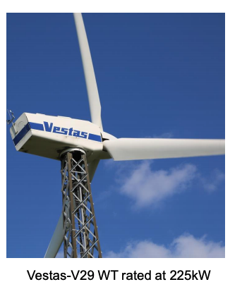
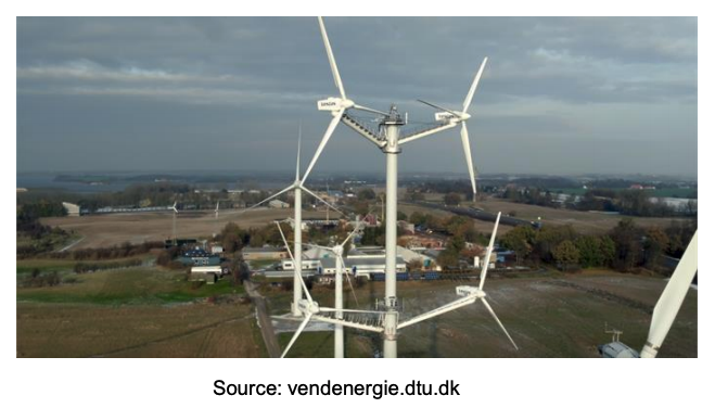
- Vestas in collaboration with DTU has proposed a 4-rotor wind turbine design proposed for future >10 MW wind turbines.
- • It increases swept area (captured power) with less overall weight and mechanical stresses.
- A proof of concept prototype was build using four V29 225kW nacelles
Offshore Wind Farms
Advantages
• Capture more power from higher offshore winds
• Little or no visual disturbance when farther from shore
• Higher capacity factors and load factors due to steadier wind flowsDisadvantages
• Higher cost due to complexity of foundation structures
• More difficult to access for maintenance
• Submarine power cables required
• When farther from shore HVDC (high voltage DC) transmission is the only option. An expensive offshore platform must be built for the HVDC power converter station -
HAWT Structure
Primary components

- Foundation
- Transformer room
- Support tower
- Rotor hub
- Blades
- Nacelle:
- Control systems
- Generator
- Power converters
- Drivetrain and Gearbox
- Instrumentation
WT blades
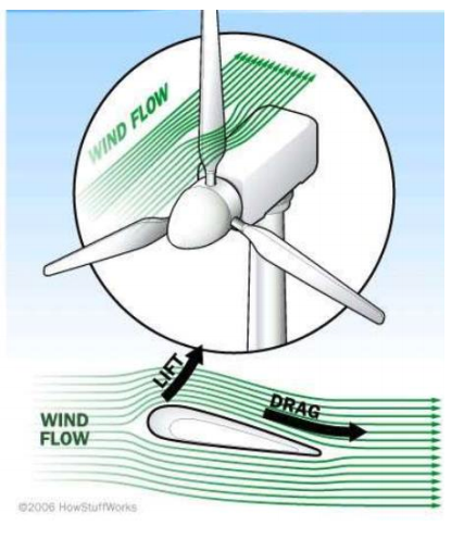
- As the air flow strikes the aerofoil blade section, the ‘lift’ and ‘drag’ force components occur.
- The blade is designed and angled such that the ‘lift’ force is significantly greater than the ‘drag’ force.
- In WTs lift-to-drag ratio can reach 120 compared to 15 for airliners.
- WT blades are made of light composite materials to minimize weight.
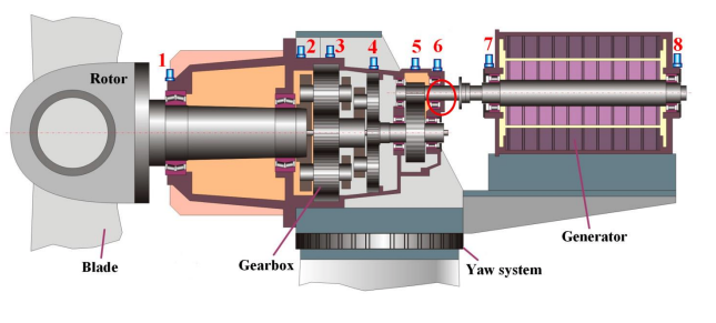
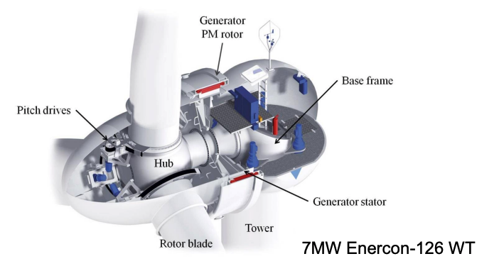
The Nacelle
Schematic view
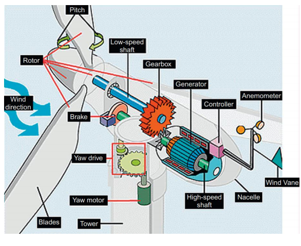
Image by Salameh, Z. “Renewable energy System Design”, chapter 3
- Mounted on top of turbine tower
- Contains the gearbox, wind generator, brakes, control and instrumentation systems
- Carries the WT rotor hub and blades
- Rotor hub
- Normally made offiberglass
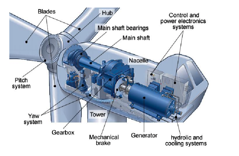
Realistic view
Generators and Power Converters
Fixed-speed wind turbines:
- Squirrel cage induction generators (SCIG) , no power converters used.
Variable speed wind turbines:
- Wound rotor induction generators with partially-rated power converter. Also called doubly-fed induction generator (DFIG-WT)
- SCIG with fully-rated converter (FRC)
- Permanent-magnet synchronous generator (PMSG-WT) with FRCWe will look in depth at these technologies next lecture!
HAWT Drivetrain
- Drivetrain transmits mechanical power from the wind turbine rotor hub to the generator with a speed step up.
- Consists of the gearbox, brakes system, low-speed shaft, and highspeed shaft.
Multi-megawatt HAWT Gearbox.
- Gearbox connects rotor hub (rotating at speeds <25 rpm) to the generator which can be rotating at 1500rpm (4 pole machine)
- 2-stage or 3-stage gearbox to achieve high gear ratios (e.g. 1:90)
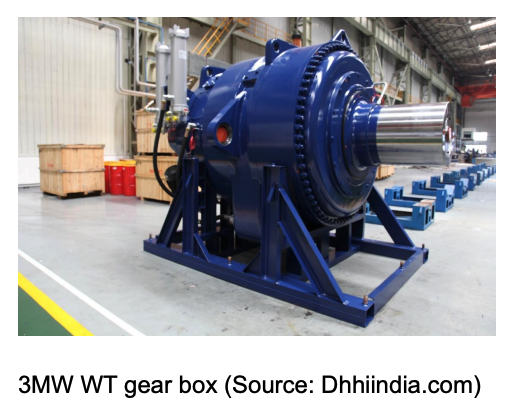
- WT gearbox is normally of planetary design
- Smaller gearboxes also required for yaw and pitch motor
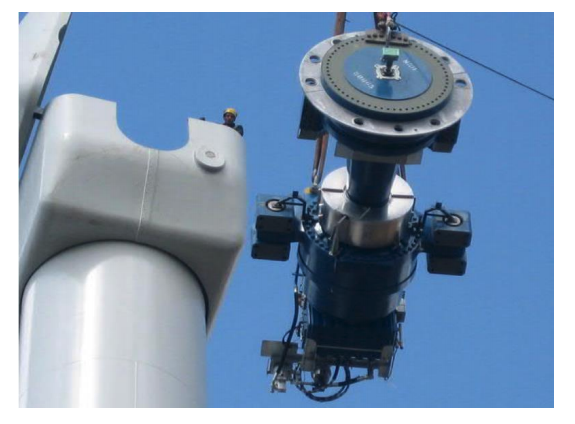
- Due to stress and wear of moving parts, gearbox requires maintenance or even replacement
- Operational experience show that WT requires gearbox replacement at least once in its lifetime (see video of replacement process).
- This is challenging for offshore wind farm installations.
- That’s why direct drive WT designs avoid use of gearbox by using low speed synchronous generators with high number of permanentmagnet poles (permanent-magnet synchronous generators)
HAWT Pitch Mechanism
- Used to maintain a certain shaft speed especially at higher wind speeds
- Can be partial-pitch angle control (part of the blade pitched) or full pitch-angle control, where the whole blade is rotated
- A pitch actuator is used to control hydraulic flow and rotate the blades
- In other mechanisms, pitch actuator (electric motor) drives a gearbox for speed transmission.
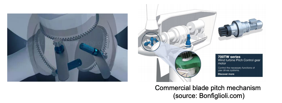
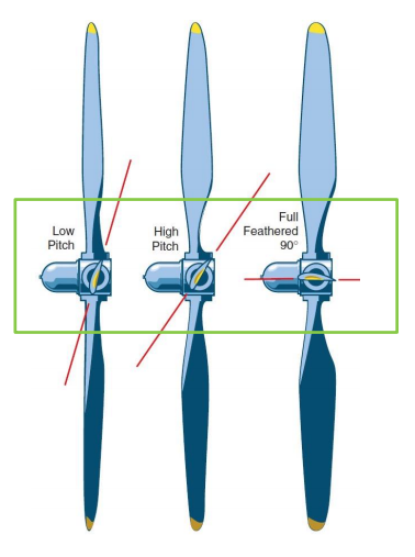
- Pitching mechanism can also be used as an aerodynamic brake system to stop the turbine in wind gusts, emergency, or planned down time.
- This can be done by pitching the blades to full-feather position, where blade section is parallel to wind flow and no power is captures (90° pitch angle).
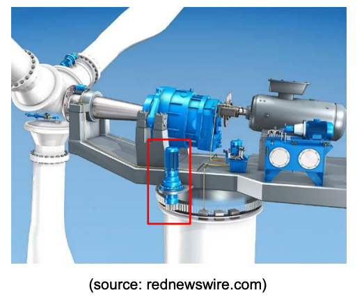
HAWT Yaw Mechanism
- Used to swing the nacelle to remain aligned with wind direction
- Receives a signal from a wind velocity sensor placed on top of the nacelle to sense wind speed and direction.
- The yaw mechanism consists of more than one unit each comprising an electric motor and a gearbox.
The WT Tower
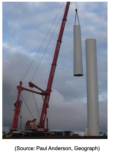
- Carries the weight of the nacelle, rotor hub and blades.
- Must be strong enough to sustain compression and drag forces
- Designed to allow access for maintenance
- Made of sections to be fixed on top of one another using cranes.
- Made of :
Tubular steel (most large WTs)
Lattice (Medium size WTs)
Guyed pole (small WTs)
Tower Foundation (onshore)
- Design depends on turbine size, height, mechanical loads, soil type and bedrock.
- Consists of: a hole, steel, concrete and backfill.

See onshore foundation construction in this time lapse below
Tower Foundation (offshore)
- Monopile foundation in shallow water up to 30m in depth.
- Jacket/tripod foundation for medium depth (up to 50m)
- Floating structures for deep waters.
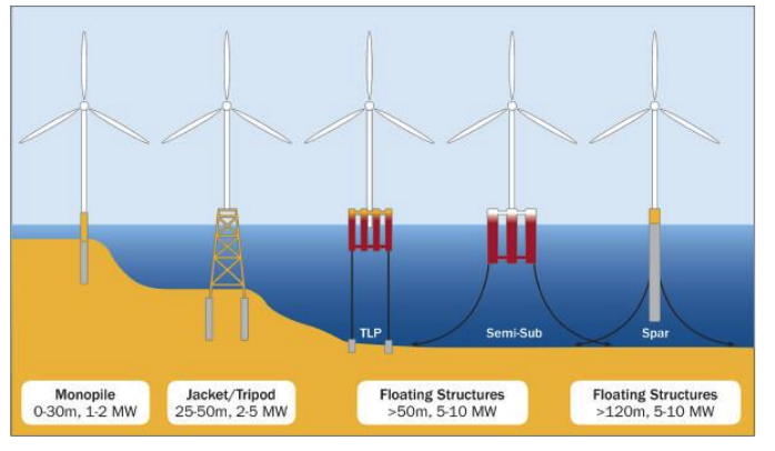
See floating foundation construction in this video
WT Structure and operation
See wind turbine structure and operation in this video
Supplementary videos on WT manufacturing, structure and operation:
WT installation
See onshore wind turbine installation
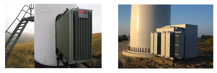
WF Power Collection Networks
- Each WT has a step up transformer placed in the base of the tower, or in a separate power room, or in some designs in the nacelle.
- The transformer steps up the voltage from 690V or 575V from the generator to typically 33kV for the medium voltage cable network in the wind farm collecting power from WTs
- For larger wind turbines (>5MW), 66kV step up transformer can be used.
WF Power Collection Networks
- Underground AC cables (onshore) or subsea AC cables (offshore) connect all turbines to a transformer substation to step up the voltage to transmission voltage levels
- Offshore, farther from the shore, AC power has to be converter to DC power for transmission to grid.
- Offshore high voltage DC converter station (HVDC) is built with step up transformer on one or more offshore platforms.
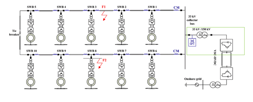
WF Power Collection Networks
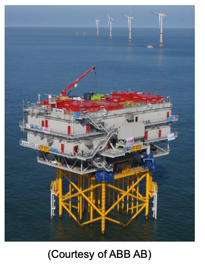
- Offshore substations host step up transformers to step the voltage to transmission levels (e.g. 150kV)
- When HVDC is used, the substation hosts also Power Converter Station.
- At high power wind farms, two substations can be built.
- Platforms require significant and costly civil engineering work.
See offshore substation construction in these videos
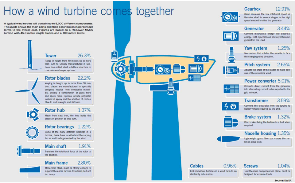
Cost of WT components
WT Wake Effect
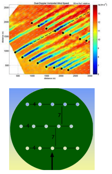
- Wake refers to the reduced wind speed downstream of a turbine after extraction of energy by an upstream turbine from the incoming wind flow
- This is associated with creation of turbulence by each WT
- As a rule of thump, WTs in a WF are normally spaced about 7 to 9 times rotor diameter in the prevailing wind direction to minimize wake effect.
See CFD visualization of WT wake in this video
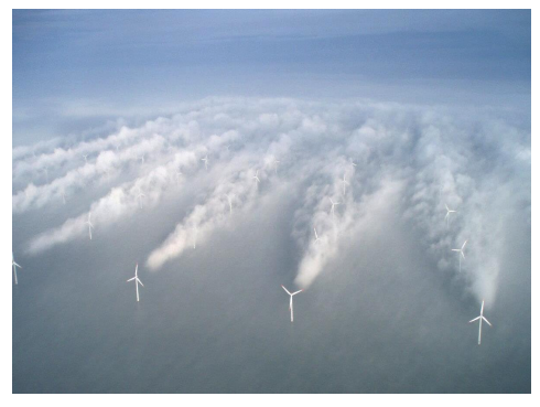
- Expectedly wind changes direction, so WT wake is unavoidable but can be minimized by sufficient spacing between WTs in the prevailing wind direction
- The image shows clouds forming in the wakes of the front row of wind turbines of the Horns Rev wind farm off the coast of Denmark. The downstream wind turbines lose 20% or 30% of their power, and sometimes even more, relative to the front row. The spacing of the turbines is 7 rotor diameters.
-
HAWT Energy Capture and Power Curves
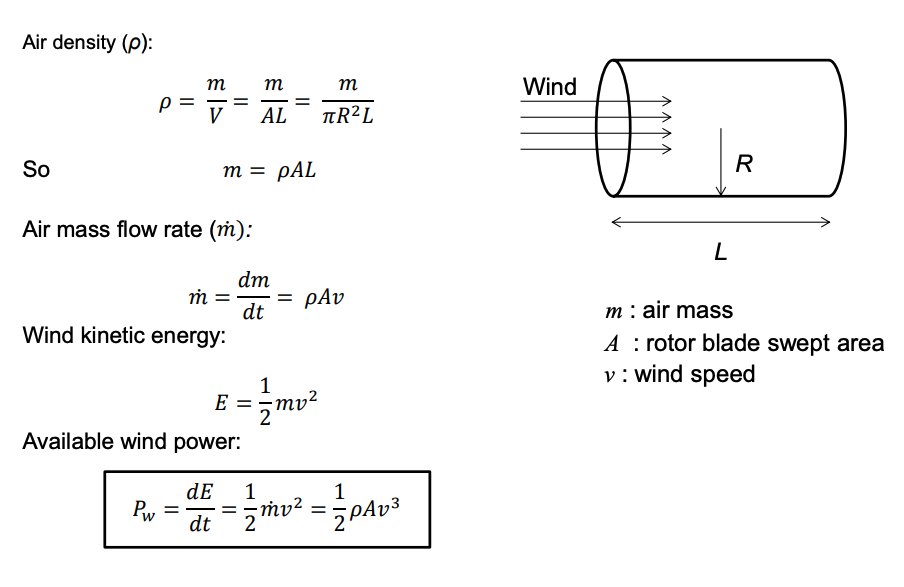
Available Wind Power
Power Captured by the WT
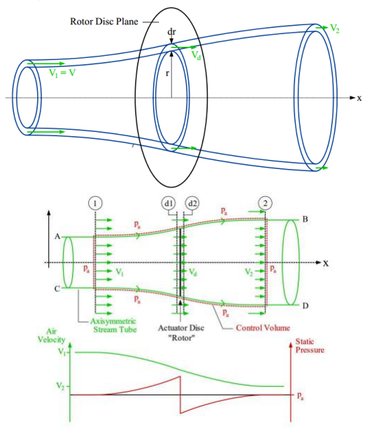
- As the wind flows through turbine blades plane, the wind expands and its speed drops from v1 to v2.
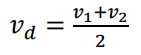
- The mean wind speed at the WT rotor plane is:
- As long as v2 is not equal to zero, the wind turbine has not captured all available wind energy.
- It is inconceivable to imagine a wind turbine can stop wind flow (i.e. reduce wind speed to zero).
So, what is the maximum portion of incoming wind power a WT can capture?
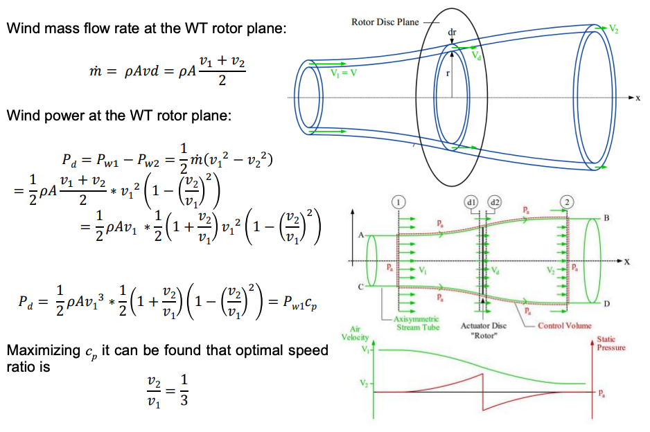
Derivation of max WT efficiency (Betz’s limit)
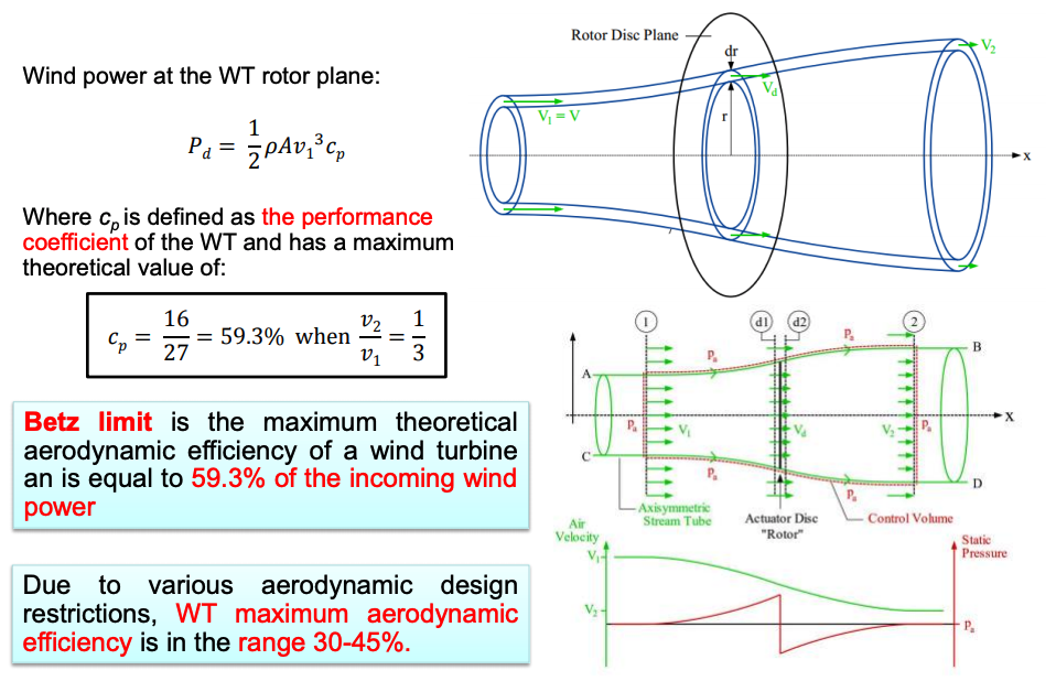
Performance Coefficient
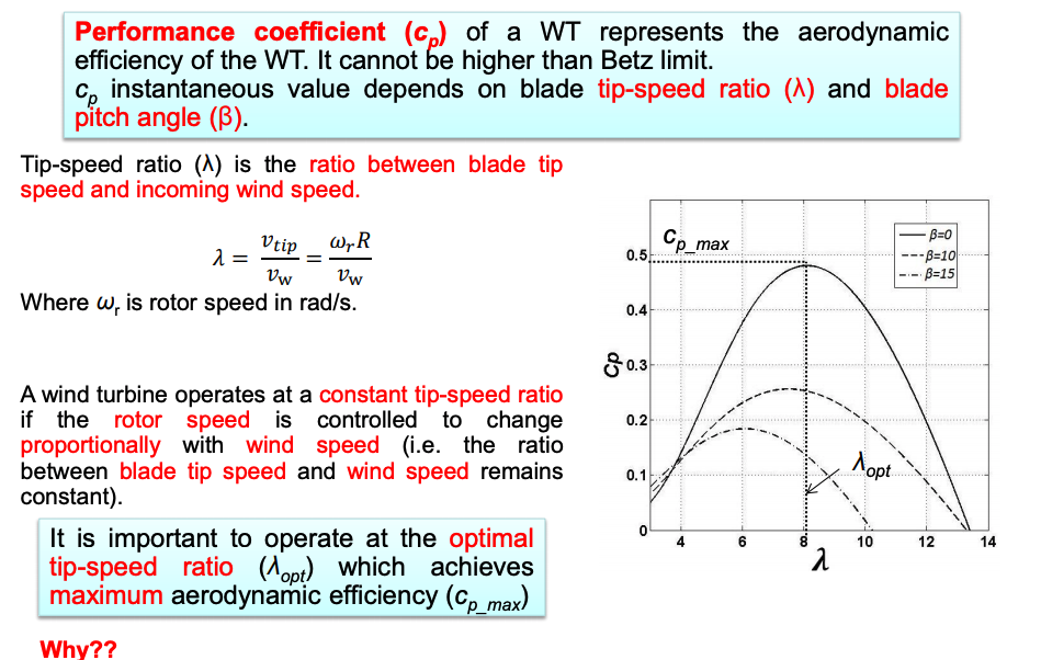
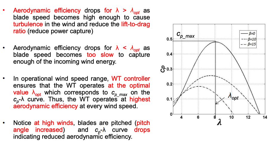
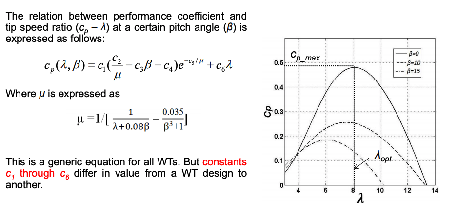
cp -λ relationship
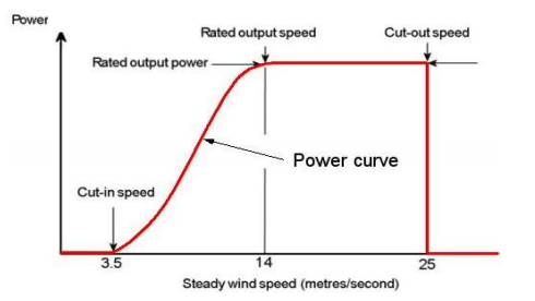
Wind Turbine Power Curve (Power/wind speed)
- WT power curve represents WT mechanical power output (or electrical power after deducting all losses) as a function of wind speed.
- Before cut-in wind speed, wind speed is too low to turn the wind turbine efficiently
- From cut-in speed up to WT rated output power, WT controller operates the WT at optimal tip-speed ratio. This is also called “maximum-power point tracking (MPPT)” region
- When rated power is reached at rated wind speed, pitch angle control operated to avoid overloading the WT. The pitching region extends till cut out speed where wind is too high for safe operation and the blades are fully-feathered and mechanical brakes activated.
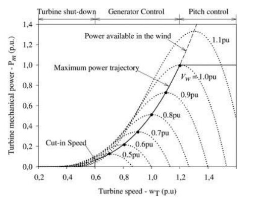
Wind Turbine Power Curve (Power/rotor speed)
- WT power curve represents controlled WT mechanical power output (or electrical power after deducting all losses) as a function of WT rotor speed.
- From cut-in speed up to WT rated output power, WT controller operates the WT at optimal tip-speed ratio. This is also called “maximum-power point tracking (MPPT)” region.
- When rated power is reached at rated wind speed, pitch angle control operated to avoid overloading the WT
-
-