-

Dr Azmy Gowaid
School of Computing, Engineering and Built Environment
Glasgow Caledonian University
Email: azmy.gowaid@gcal.ac.uk
Indicative reading
- Salameh, Z. (2014). Renewable energy system design. >Waltham, Massachusetts:
Academic Press. (Available online)
Chapter 3 sections 3.5.5 up to 3.6.4
- Fox, B., Flynn, D., Jenkins, N., Milborrow, D., Bryans, L., Anaya-Lara, O., O’Malley, M., et al. (2014).
Wind power integration : connection and system operational aspects. (Second edition) (Available online)
Chapter 3 sections 3.5 and 3.6 - Salameh, Z. (2014). Renewable energy system design. >Waltham, Massachusetts:
-
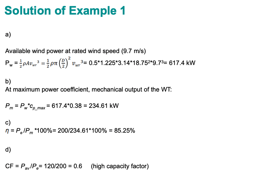
Example 1
A wind energy system has the following parameters:
Rotor turbine diameter, D = 37.5 m
Wind turbine maximum power coefficient, Cp_max = 0.38
Cut-in wind speed, Vwi = 5.4 m/sec
Rated wind speed, Vwr = 9.7 m/sec
Cut-off wind speed, Vwo = 17.9 m/sec
Air density, ρ = 1.225 kg/m3
Synchronous generator rated power output, Pe = 200 kW
a) Calculate the available power in the wind at rated wind speed
b) If the wind turbine operates at maximum power coefficient at rated wind speed, then calculate the mechanical power extracted from the wind at rated wind speed Pm
c) Calculate the combined gearbox and generator efficiency.
d) Calculate the generator capacity factor, CF, if the average power output of the generator is Pav = 120 kW
- Click here to view the Solution to Example 1
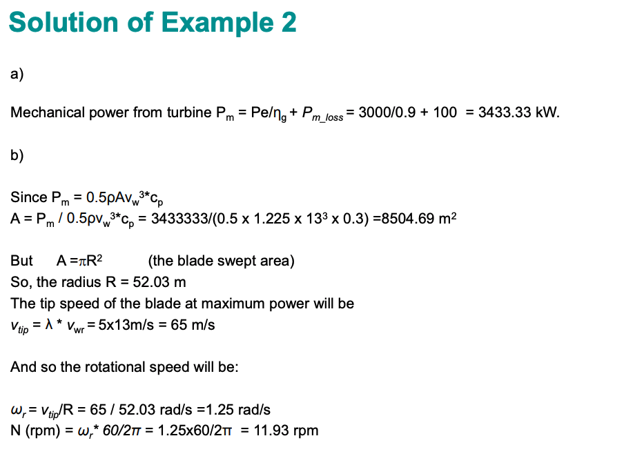
Example 2
A WTG system is assumed to have the following characteristics:
- The maximum electrical power output Pe =3 MW,
- The mechanical conversion (gearbox) loss is Pm_loss=100 kW,
- The mean generator efficiency is ηg = 90%
- Tip-speed-ratio (TSR) λ = 5
- Performance coefficient cp =0.3
- Maximum power is produced when wind speed reaches 13m/s,
- The air density is 1.225 kg/m3
Determine:
a) The maximum mechanical power output from the turbine.
b) Blade speed in rpm at maximum power output.
- Click here to view the Solution to Example 2
-
Wind Turbine Generators
How is WT Speed Fixed?
- Rotation of WT rotors follows the laws of rotational motion.
- The rotational speed becomes constant only under zero resultant torque
Tm - Te = J$\dot{\omega}$
Where
Tm - Mechanical torque resulting from lift force on WT blades
Te - Electrical torque resulting from generator
J - Combined inertia of blades, rotor hub, and drive train
$\dot{\omega}$ - Rotational acceleration
So WT speed can be fixed or made variable in a controlled manner only by the existence of a controllable electrical torque from the generator to counteract mechanical torque acting on the blades
WT runaway (uncontrolled acceleration) can result from very high mechanical torque or disconnection from grid (absence of electrical torque). Mechanical and/or aerodynamic brakes must be used to avoid failure.
See this video of runaway failure.
Stall Controlled Wind Turbines
Stall is an alternative way to pitch control to avoid overloading the WT at high wind. There are two types of stall control for WT designs:
Passive stall control:
- Unlike pitch controlled WTs, passive stall controlled wind turbines have the rotor blades bolted onto the hub at a fixed angle.
- The geometry of the rotor blade is designed to ensure that at high wind it creates turbulence at the blade, leading to significant reduction of the lift force (stall)
- Passive stall avoids moving rotor parts and complex mechanisms, but requires complex aerodynamic blade design.
Active stall control:- Active stall WTs have also pitchable blades similar to pitch controlled WTs.
- At high wind, blades are pitched in the opposite direction of that in a pitch controlled WT and stall occurs.
- The WT can be run almost exactly at rated power at all high wind speeds whereas passive stall reduces wind power the higher the wind speed.
Fixed Speed Wind Turbines
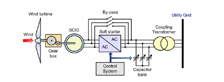
- The wind turbine rotor speed is almost fixed regardless of the wind speed and determined by the frequency of the supply grid, the gear ratio and the generator design (number of poles).
- It is characteristic of fixed-speed wind turbines that they are equipped with a squirrel cage induction generator (SCIG) that is directly connected to the grid.
- A soft-starter is used for smooth grid connection and disconnection and acapacitor bank used to reduce reactive power required from the grid.
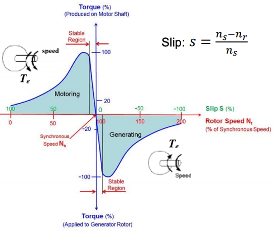
- Below synchronous speed, induction machines operate in motoring mode according to the shown torque-speed characteristics. The produced torque drives the rotor (positive torque)
- When driven above synchronous speed, induction machines operate in generating mode. The produced torque counteracts the rotation (negative torque)
- FSWT induction machine operates in the generating mode within -1% or -2% slip to stay within stable operating region.
- In the stable region, torque is proportional to slip which is very important for stable operation. WHY?
- When the mechanical torque increases due to higher wind, slip increases.
- In stable region, a large increase in electrical torque results from a small increase in slip
- This brings FSWT speed to stability at slightly higher slip.
- The limit of the stable region corresponds to the rated generator torque beyond which SCIG goes into instable region with possibility of runaway.
- Induction machines are more efficient the steeper the torque-speed curve is in the stable region. So an efficient FSWT will have very small stable region (-1% or -2% slip range)
Fixed Speed Wind Turbines (FSWT)
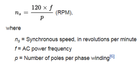
Effectively, FSWT speed changes in a very narrow range of 1-2% slip. For example, if ns = 1500rpm, SCIG rotor speed would be 15-30 rpm above synchronous speed. This corresponds to lower than 1 rpm speed variation at the WT rotor hub
- FSWTs operate at the optimal tip speed ratio (maximum aerodynamic efficiency) around one wind speed.
- To increase power extraction of FSWTs, they are often operated at two fixed speeds by using two SCIGs each with a different number of poles (two different synchronous speeds).
- Often one SCIG is used with two sets of winding each would for different number of poles. Pole changing methods can alternatively be used in the stator winding of SCIG.
Fixed Speed Wind Turbines (FSWT)
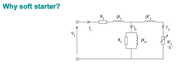
- Induction machines are not allowed to start from stand still (s = 1) with full voltage to avoid high inrush currents and mechanical stress (see equivalent circuit)
- Soft starter is a power electronics converter used to reduce the inrush current and transient torques during connection or disconnection of the generator to the grid.
- To start the FSWT, the rotor hub is allowed to accelerate under the mechanical torque only until it exceeds synchronous speed. The soft starter then connects the SCIG smoothly to the grid over a few voltage periods by control of thyristor firing angles.
- To shut down the FSWT, the soft starter disconnects the SCIG smoothly from the grid before rotor hub speed drops below synchronous speed to avoid motoring action.

- Whether operating as generator or motor, induction machines build their rotary magnetic field using reactive power from the power supply.
- The reactive power is dependant on the value of slip. Higher slip leads to more consumption of reactive power.
- Reactive power consumption is not good for voltage stability at the point of connection to grid
- That’s why a capacitor bank is normally connected to improve the power factor at the connection point (reduce reactive power consumption)
Advantages and disadvantages:
Advantages
- Simple and rugged generator design.
- No need for rotor brushes as in a wound rotor induction generator (WRIG)
- No complex speed and torque control required.
- No costly power converters to process and condition generated power
Disadvantages
- 20-30% less annual energy harvest compared to variable speed WTs (VSWTs).
- High mechanical stress on WT components as large wind fluctuations are seen by the WT as mechanical torque fluctuations due to fixed speed.
- Reactive power consumption from the grid leading to less voltage stability.
- Switched capacitor bank help least when most needed since delivered VARs reduce with lower voltage and frequency (Qc = ωCV2).
- Capacitor banks are discrete with slow switching >150ms and cause harmonic problems, such as ferro-resonance.
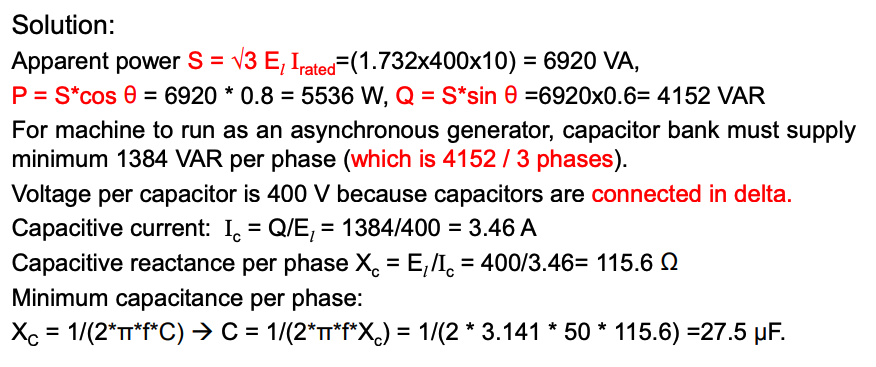
Example on FSWTs
A 1467 r/min, 400 V, 3-phase induction machine is operated as an asynchronous generator in a fixed speed wind turbine. Full-load current of the machine is 10 A and full-load power factor is 0.8. Determine the required capacitance per phase if A capacitor bank is connected in delta to supply generator’s excitation?
- Click here to view solution.
Variable Speed Wind Turbines (VSWT)
- FSWTs are normally called Type-1 WTs
- VSWTs have 20-30% higher annual energy yield due to the capability for maximum power extraction.
- Reduced mechanical stresses as power fluctuations are almost absorbed through speed variation
- VSWTs has three types so far:
Type-2: Limited VSWT, Optislip® controlled (10% speed variation above ns)
Type-3: DFIG-based VSWT (±30% speed variation around ns)
Type-4: PMSG-based VSWT or Direct-Drive WT ( >±30% speed variation around ns)
Optislip®-Controlled Limited VSWT
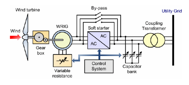
- Similar to design and operation principles of FSWT but with variable resistance inserted in rotor circuit for speed control. For that it uses a wound rotor induction generator (WRIG)
- Has been introduced by the Danish manufacturer (Vestas Wind Systems) in the mid 1990s
- The total rotor resistance is controllable via the variable additional resistors.
OptiSlip® Concept: Variable resistance is changed by an optically controlled converter mounted on the rotor shaft. The optical coupling eliminates the need for costly slip rings that need brushes and maintenance
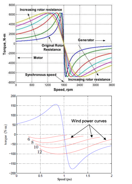
- The stable operating region of the torque-speed relationship extends with higher rotor resistance.
- This WT has wider speed range before reaching rated torque (typically up to 10% slip above ns).
- Higher utilization of wind power due to the variable speed capability
- Reduced (but not eliminated) torque fluctuations compared to FSWTs.
- OptiSlip® technology is more complex and expensive.
- Lower efficiency due to losses in external resistance.
- No capability of independent active and reactive power control like other VSWT technologies.
- It was found out that excessive power loss in the rotor circuit is the barrier to increasing OptiSlip® VSWTs speed range beyond 10% supersynchronous.
- This is a general characteristic of induction machines to have more rotor power loss by increasing slip. The rotor power loss is called “slip power”
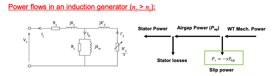
- Note: Since the slip is negative above synchronous speed, a minus sign is introduced so that rotor power loss “slip power” is a positive number
- Rotor losses (slip power) being proportional to slip means that for 20% slip (i.e. s = – 0.2), about 20% of input mechanical power to the generator is lost
What can be the solution to increasing slip (speed range) without more rotor power losses?
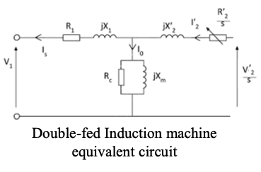
Doubly-Fed Induction Generator VSWT
Operation Principles
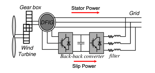
- DFIG-WT design emerged from the possibility of recovering the slip power (otherwise, power lost in the rotor) using power electronic converters connected to the rotor circuit to inject the slip power back into the grid.
- Back-to-back converters are used for AC/DC then DC/AC conversion.
- The converters power rating is subject to the maximum operating slip.
In commercial DFIG-WTs, converters of power rating no more than 30% of generator power rating are sufficient to accommodate slip power for a slip range up to 30%.
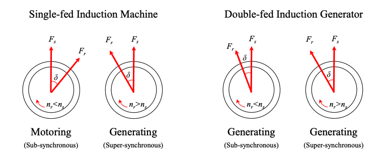
Can you use the DFIG back-to-back converter to operate the induction machine as a generator for sub-synchronous speeds (nr < ns ) as well ?!!
- Converters are able to control the induction machine to operate as a generator for subsynchronous speeds.
- The rotor-side converter injects voltage into the rotor circuit to control the rotor field angle with respect to stator field in a way that operates the machine as a generator also when nr < ns (i.e. subsynchronous speed)
Structure and Capabilities
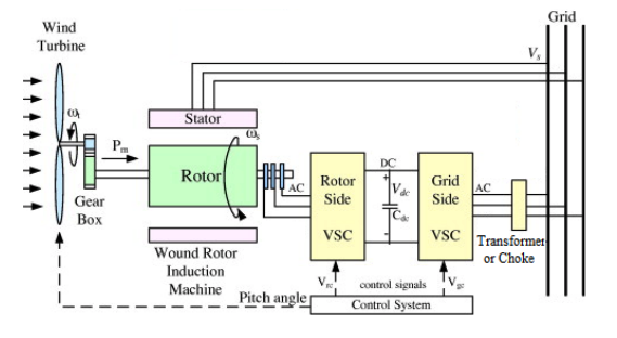
- The DFIG consists of a wound-rotor induction generator (WRIG) with the stator windings directly connected to the constant-frequency three-phase grid.
- Rotor windings are connected via slip-rings to variable frequency back-to-back converters; the rotor-side converter (RSC) and grid-side converter (GSC).
- Both converters are connected via a DC-link capacitor.
- Chokes (smoothing inductors) are connected between GSC and the grid to filter out harmonics.
- A transformer is used instead of the choke if rotor circuit voltage is designed to be higher than stator circuit voltage to reduce currents and losses in power converters.
RSC is controlled to:
- Control DFIG rotor speed / electrical torque to achieve maximum power tracking (operation at optimum tip speed ratio) within ±30% slip.
- Achieve unity power factor operation (i.e. near zero reactive power consumption from the grid regardless of slip)
- Magnetizing the machine at start up through the rotor circuit.
GSC is controlled to:
- Maintain a constant DC-link voltage while slip power is exchanged with the grid at unity power factor (no reactive power consumption from grid)
- Support the grid voltage in case of disturbance acting as a STATCOM or SVC (reactive power support).
Stator and Rotor Power Flows
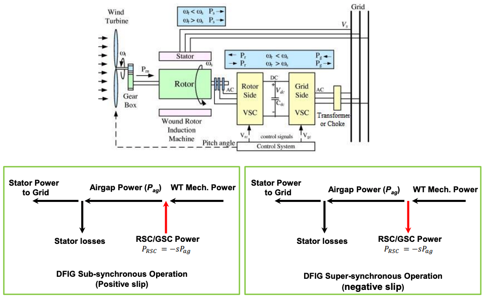
To retain a constant DC-link voltage:
- The power passed to the RSC from the generator should equal to the power transferred to the grid through the GSC (neglecting the converter losses).
- Thus, while real power flows from the DFIG to the RSC, the GSC should be operated as an inverter and controlled in such a way as to deliver the same amount of real power to the grid.
- While real power flows from the RSC to the generator (sub-synchronous operation), the GSC should be operated as a rectifier and controlled in such a way as to receive the same amount of power from the grid.
Maximum Power Point Tracking
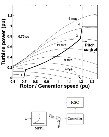
- Within its operating range from 0.7pu to 1.2pu the DFIG-WT operates at the optimum tip speed ratio where the operating point follows the MPPT curve (section 2-3 of the curve).
- Rotor speed is measured (not wind speed) and a lock-up table representing the MPPT curve is used such that RSC adjusts DFIG electric power output to track maximum power point at the current wind speed.
- Since the WT cannot exceed 1.3pu speed not to overload the power converters, pitch control is activated at 1.2pu rotor speed to give enough speed margin for the (relatively slow) pitch mechanism to operate.
RSC and GSC Structure and Operation
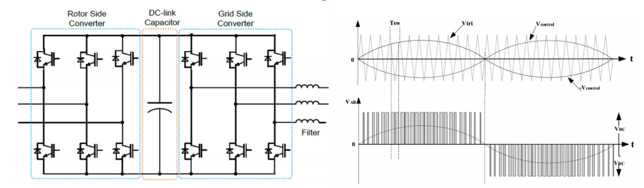
- Each AC/DC converter is a two-level voltage source converter (VSC) using IGBT power electronic switches.
- RSC and GSC use Pulse Width Modulation (PWM) to convert the DC link voltage to AC voltage waveforms of low harmonic content. Controllers are based on Vector Control techniques.
- GSC voltage and current are at the grid frequency (ƒg ) while the RSC voltage and current are at the slip frequency.
𝑓𝑅𝑆𝐶 = 𝑠𝑓g
DFIG Currents and Voltages
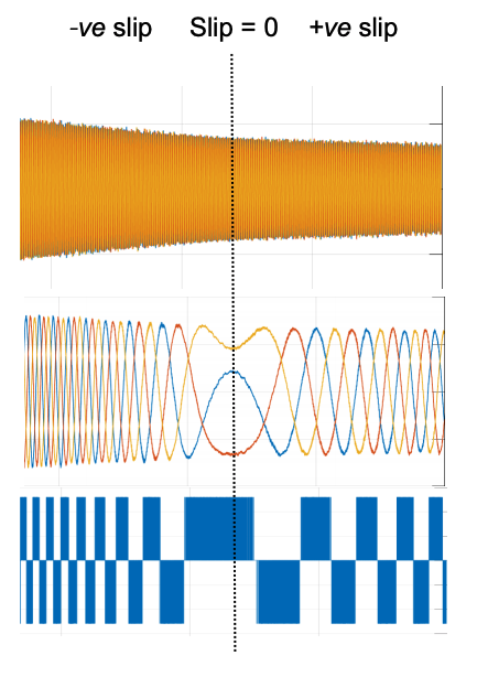
These waveforms represent the operation of a DFIG-WT slowing down from supersynchronous operation to sub-synchronous operation:
- Stator currents (upper plot): although reducing in magnitude as WT power drops, they remain at grid frequency.
- Rotor currents (middle plot): At slip frequency. The frequency changes with change of slip.
- Zero-frequency RSC current (near-DC) is noticed when WT rotates around synchronous speed
- RSC PWM voltages can be seen also to change their frequency with WT speed.
Advantages
- Variable speed operation allows for higher wind energy capture
- Decoupled control of active and reactive power allow unity power factor operation
- Use of Power converters of partial rating saves costs of fully rated converters.
Disadvantages
- Need for Slip rings and brushes. Brushes wear out and require replacement.
- Need for 3-stage gearbox for speed transmission. Gearboxes are of lowreliability and require regular maintenance and even replacement.
- Speed range limited to ±30% of synchronous speed to avoid extra cost of power converters.
- Induction machines design not easily scalable to higher power and voltage levels
-
Evolution of VSWTs
Full-rated Converter VSWT
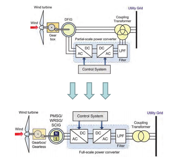
- SCIG can be used in a WT with full-rated converters (FRC-WT) due to continuously dropping cost of power electronics.
- This connection decouples stator frequency from the grid frequency.
- Back-to-back converters convert stator frequency and voltage to grid frequency and voltage.
- The generator synchronous speed is not constant and is allowed to change.
- As the WT speed changes, the FRC alters the stator frequency (and synchronous speed) such that the SCIG keeps within stable operating region (narrow slip range above synchronous speed).
- Gearbox is still needed as in previous types of VSWT.
- Gearless (direct drive) operation is not possible as induction machines are complex to design for low rotational speed (high number of poles).
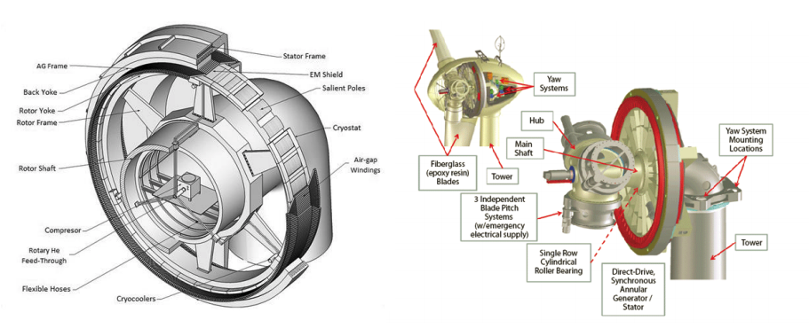
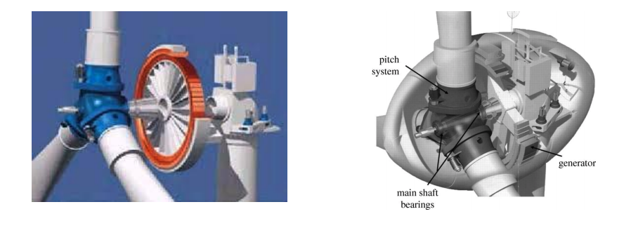
Direct-Drive Wind Turbines
Permanent magnet synchronous generator (PMSG)
- To scale FRC-WTs up in power and avoid gearboxes, synchronous generators with high number of poles are used such that PMSG rotates at rotor hub speed.
- Permanent magnets are used in the rotor to give the synchronous generator a property of self-excitation, which reduces complexity of rotor circuit.
- In a PMSG-WT, the PMSG is not directly connected to the gird, and is allowed to operate at variable range of rotational speeds
- So in a PMSG-WT, the PMSG is not operating at the synchronous speed, rather ALL SPEED VALUES OF THE PMSG ROTOR ARE SYNCHRONOUS SPEEDS.
- Power converters connected to the PMSG stator convert the stator frequency to the grid frequency.
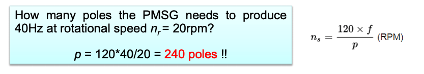
- In this case, 20rpm is a synchronous speed for the generator. The power converter converts the frequency of voltages/currents from 40Hz to 50Hz (grid frequency).
- In the PMSG, the efficiency is higher than in the induction machine, as the excitation is provided without any energy supply
- Permanent magnets are rare earth material, hard to work, and intolerant to high temperature.
- Direct-drive WTs have smaller nacelle generally due to absence of gearbox and the complex drive-train. Power converters normally placed at ground level.
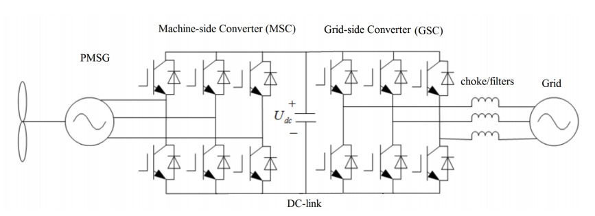
PMSG-WT structure
- Unlike DFIG-WTs, the power converters are connected to the stator and full generated power flows through the converters. So the power converters must be rated to the generator ratings (not 30% like in DFIG-WTs)
- PMSG-WT operates at a wider range of wind speeds than DFIG-WT along a similar maximum power point tracking curve.
- Three phase two-level IGBT bridges are used.
Power converters and control
Vector control techniques are used to control the operation of the wind turbine.
The MSC is responsible for:
- Control of the PMSG electric torque for operation along the MPPT curve.
- Decoupled active and reactive power control.
The GSC is controlled to:
- Maintain the DC-link capacitor voltage in a set value.
- Maintain the converter operation with a desired power factor (usually unity PF).
More on design and practical aspects of Direct Drive WTs in this video
Advantages
- Wider variable speed operation allows for higher wind energy capture
- Higher reliability of mechanical parts due to absence of gearbox
- Decoupled control of active and reactive power allow unity power factor operation
- Higher level of reactive power support to the grid under fault w.r.t DFIG-WT
- Scalable to higher power levels than DFIG-WT.
Disadvantages
- Permanent magnets are sensitive to temperature/heat (demagnetization).
- High cost of rare-earth magnets
- Use of Full-rated power converters adds to the cost and losses.
- No control on excitation possible from rotor circuit.
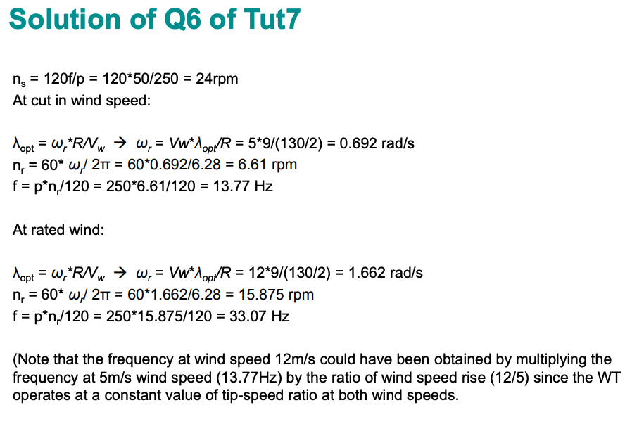
Question 6 in Tut 7
A 3MW synchronous machine has been specifically manufactured for a wind turbine.
Permanent magnets are mounted on the rotor such that the machine has 250 poles.
a) What would be the generator speed if connected directly to 50Hz grid?
b) The machine is connected directly to the rotor hub of a wind turbine. Back-to-back fullrated power converters are used to interface the stator to the grid and run thewind turbine along maximum power point tracking curve. If the cut-in wind speed is 5m/s and rated wind speed is 12m/s, find the lowest and rated frequency the synchronous generator produces if optimal tip-speed ratio is 9 and rotor diameter is 130m.
- Click here to view the solutions
- Insert Content Here 7