08
-
Guidance of study for Week 8
- (i) Please review 8.1 to 8.7 inclusive and the reference notes for this week 8 is taken from Chapter 40, “Power Systems”. And “The per-unit system”. Both of these sets of notes are contained within the folder, ”Learning Resources” of GCU learn.
- (ii) “Quiz No: 2 Sources of Energy” is available within the “Quizzes” folder of GCU learn. Use of the internet is permissible in answering these multiple choice questions.
- (iii) HOMEWORK: - Task 3 and Task 4 should now be attempted. Each Task has 4 exercises. You are to complete all of the 4 exercises, but to only submit 2 (max 2 pages in length) to your tutor for feedback.
- (iv) Tutorial questions to be attempted.
- Any problems / questions. Please contact your tutor
-
Introduction
- All industrialized countries rely heavily on electricity supply systems. Such power systems are complex interconnected networks of overhead lines, underground cables and transformers for the transmission and distribution of electrical energy over long distances from power station to consumers. Power system analytical techniques have been developed in order to design and operate efficient power systems. This chapter introduces some of these methods and explains their purpose.
- One of the main design, and operation, issues involves voltage drop along long current-carrying transmission lines. In order to carry large load currents economically but without excessive loss, circuit impedance has to be carefully ‘managed’ and therefore conductor cross-sections need to be appropriately sized. This chapter introduces the calculation of voltage drops in electricity supply circuits.
- The other major issue discussed is the calculation of fault currents in power systems. It is the circuit impedance, between generators and a fault location, which limits the short-circuit current that flows. This, in turn, determines the rating of circuit breaking equipment, installed to minimize damage to system equipment. This chapter will enable you to make simple calculations of fault current.
- Power system engineers use a per-unit method for these analyses. It considerably simplifies such calculations in complex, interconnected networks operating at many different generation, transmission and distribution voltages. This chapter compares the ‘ohmic value’ and the ‘per-unit’ methods of calculation. By the end of the chapter, you will be able to carry out volt-drop and fault current calculations using the per-unit method
- By the end of this week’s notes, you will be able to carry out volt-drop and fault current calculations using the ohmic and per-unit methods of calculation.
System Representation
- Individual components of power systems are Generators, which supply the electrical energy. Transmission and representation distribution networks of overhead lines and underground cables deliver the energy to consumers where all manner of electrical loads, from motors to TVs, use it.
- Transformers initially raise the generated voltage for efficient transmission over long distances and thereafter decrease the system voltage for local distribution and utilisation.
- As has also been discussed in week 7, electrical energy is most efficiently supplied by three-phase systems. The electrical loads are arranged to ensure that the currents in each of the three individual phases are roughly equal. In this condition, a power system is said to be balanced.
- In fact, power systems are normally well balanced and can, for many purposes, be both more simply and accurately represented by a single-phase diagram. It is often the practice also to omit the neutral line – no current flows in it in a balanced three-phase system – leaving a single-line diagram. Both the single-phase representation with neutral and the single-line diagram are commonly used.
- The diagram below represents how electricity is delivered to the customer (UK)
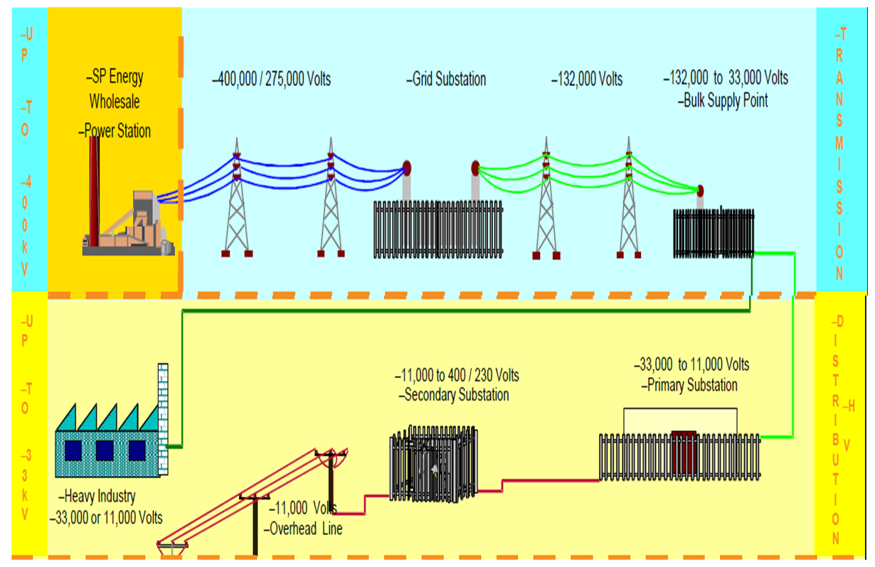
- A simplified diagram of a three-phase supply system is depicted is shown below. The voltages shown are typical UK network line to line voltages.
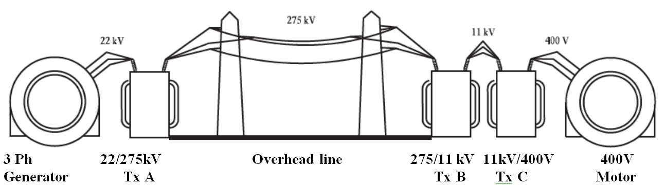
- It is necessary to represent this as a single-phase diagram. In order to do this, we have to consider the representation of the transformer and of the transmission line.
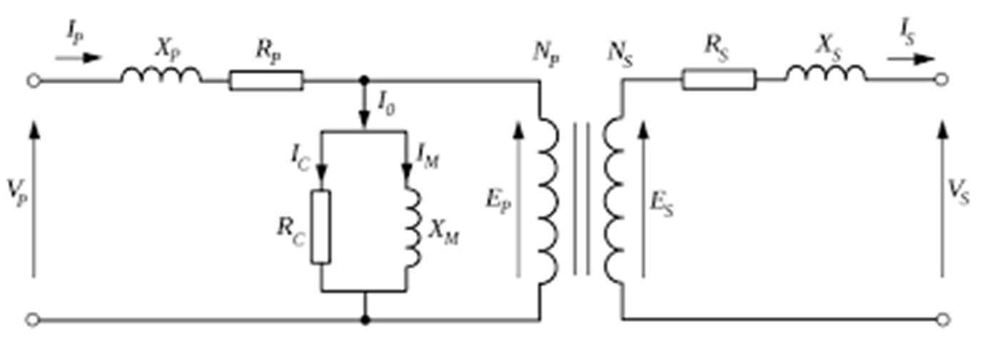
- Ideal equivalent circuit of a transformer (Tx)
Representation of the transformer
- We will ignore the parallel magnetising branch, since load and fault currents through series impedance elements are of most concern to us in the analysis to be carried out. We can therefore use the simplified equivalent circuit. The equivalent impedance of the primary and secondary windings can be referred to either the primary or the secondary of the transformer, whichever is most convenient for the power system under consideration.
- Simplified equivalent circuit of a transformer (Tx)
Representation of the transmission line
- A transmission line has series resistance, series inductive reactance, shunt capacitance and leakage resistance which are distributed evenly along its length. Except for long lines, the total resistance, inductance, capacitance and leakage resistance of the line can be concentrated to give a ‘lumped-constant’ circuit which simplifies the calculations.
- The particular ‘lumped-constant’ circuit used depends on the length of the line and the required accuracy of the calculations. For the purposes of this introduction to power system calculations, we will consider a representation which is accurate for short transmission lines up to about 80 km in length. For this length of line, the shunt capacitance and leakage resistance can be ignored, as shown below in the diagram. It should be noted that this assumption is not valid for unloaded lines when the shunt capacitance dominates.
- Transmission line has:
- (i) series resistance
- (ii) series inductive reactance
- (iii) shunt capacitance and
- (iv) leakage resistance which are distributed evenly along its length.
- Concentrated together “lumped-constant” to simplify calculations.
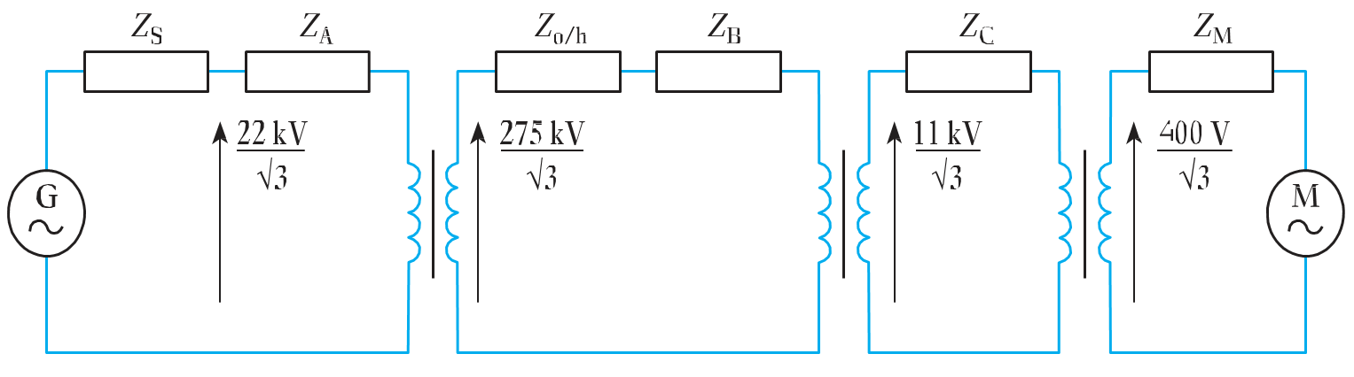
- Equivalent Circuit Diagram of Simple Power System
- Equivalent circuit of simple power system.
ZS - generator or source impedance ZA - transformer impedance referred to 22 kV Zo/h - 275 kV transmission line impedance ZB - transformer impedance referred to 275 kV ZC - transformer impedance referred to 11 kV ZM - motor impedance 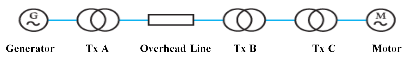
- Single Line Diagram of Simple Power System
-
Power system analysis
- Required for a large number of different purposes. These include:
- System design and control to maintain consumer voltage at statutory levels. (Effected by conductor sizing and transformer tap changer position.)
- Fault calculations to ensure that the maximum fault current can be inter- rupted by circuit breakers or fuses and that large fault currents cause the minimum of damage to the power system.
- Design of protection systems to ensure faulty circuits are switched off rapidly (<20 ms) to prevent damage and to ensure only the faulty circuit is switched off to minimize supply disruption.
- System design and control to maintain frequency within + or - 0.5 per cent.
- To ensure sufficient generation is available to meet the expected demand
– load forecasting.- To ensure that loads are supplied by the most efficient arrangement of generators – load scheduling.
- We shall consider for this week 8, only the first two of these topics – the calculation of voltage drops and the calculation of fault currents in supply networks.
Voltage-drop Calculations
- Consider the equivalent circuit of a short transmission line below, where VS is the sending-end voltage and VR is the receiving-end voltage.
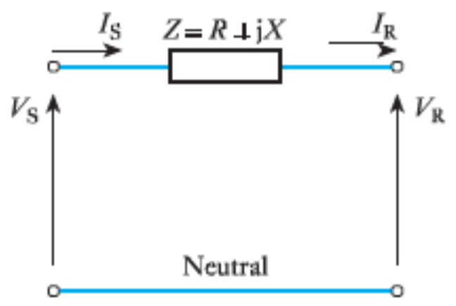
- Equivalent circuit of a Transmission Line
- The above diagram is used to represent a single phase of a balanced three-phase system. VS and VR are phase to neutral voltages calculations.
- Since there are no parallel branches, the current at the sending end (IS) and that at the receiving end (IR) are the same.
- Hence the two circuit equations are
- V_S = V_R + ZI_R
- I_S = I_R
- The current is calculated from the three-phase power delivered
- P = 3V_RI_R\;_{cos} \theta
- The phasor representation is shown below.
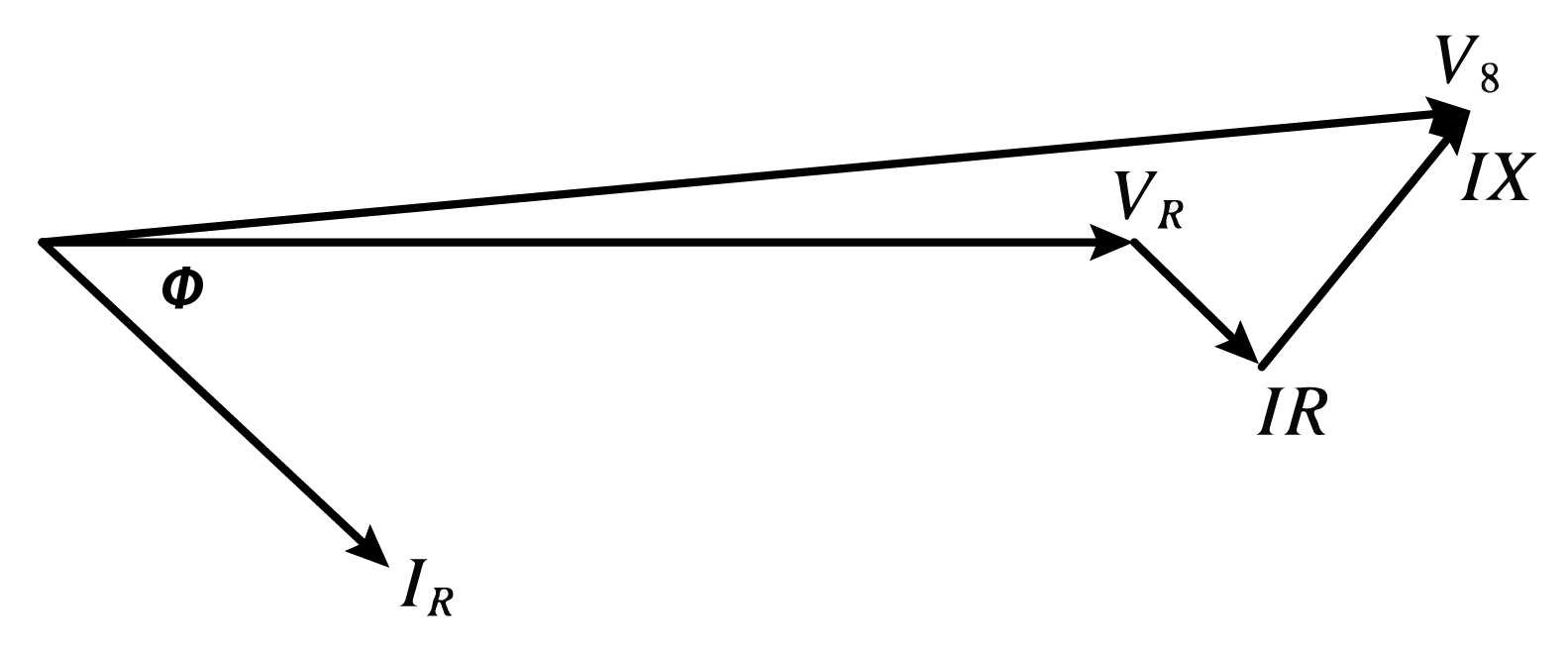
- Figure 40.2
- It is clear from these ideas that the impedance of networks has a considerable bearing on power system design and operation. Supply authorities have a statutory obligation to consumers to maintain voltage levels to within a few per cent of the declared supply voltage. (In Europe this is now 230 V (phase to neutral) with a permissible variation of (10 per cent and –6 percent.) This can be problematic.
- First, voltage drops down long transmission lines have to be minimized by choice of conductor cross-section and impedance. At the same time, it has to be realized that lines and cables having conductors of larger cross-section are much more expensive, so economic design is important.
- Secondly, the variation of load current throughout the 24-hour day means that the voltage drop in a network also varies. In order to support the voltage to consumers during periods of heavy demand and to reduce it during periods of light loading, network transformers have tap- changing gear which can automatically vary the transformer turns ratio, and hence maintain the secondary voltage output according to system load requirements. It should be understood though that tap changers are designed to accommodate only a small range of voltage variation and do not compensate for poor system design.
Example 1
- An 11 kV, three-phase, 50 Hz line of resistance 3 Ω / ph and reactance j7 Ω /ph supplies an 11 kV/400 V transformer having negligible resistance and reactance of j2 Ω/ph referred to 11 kV. The transformer supplies a 400 V feeder of resistance 0.01 Ω/ph and reactance j0.005 Ω/ph. If VR, the receiving-end voltage, is 400 V, calculate VS, the sending-end voltage, when the three-phase load delivered is 250 kW at unity power factor.
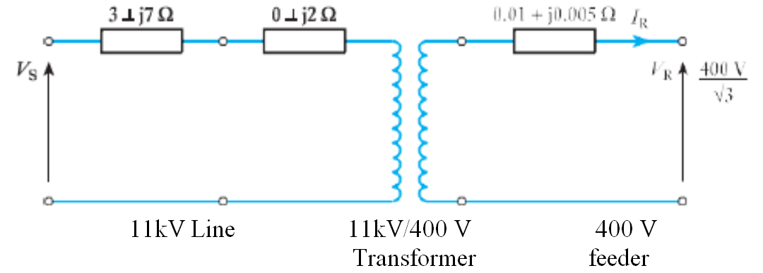
- 🔗 Solution to Example 1
Example 2
- A 400 V, three-phase induction motor takes a current of 300 A per phase at a power factor of 0.8 lag. It is supplied by a length of 275 kV overhead line of impedance (1 + j10) Ω/ph, a 275/11 kV trans- former of impedance (2 + j15) Ω/ph referred to its primary and an 11 kV/400 V transformer of impedance (2 + j10) Ω/ph referred to its primary. Determine the sending-end voltage if the voltage at the motor is 400 V.
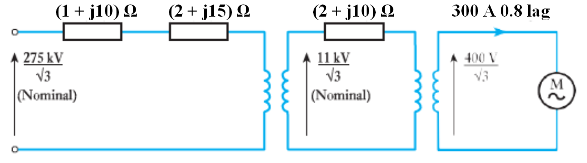
- 🔗 Solution to Example 2
-
The Per-Unit System
- In the analysis of power networks, instead of using actual values of quantities it is usual to express them as fractions of reference quantities, such as rated or full-load values. These fractions are called per unit (denoted by p.u.) and the p.u. value of any quantity is defined as
- actual value (in any unit)
- base or reference value in the same unit
- Some authorities express the p.u. value as a percentage. Although the use of p.u. values may at first sight seem a rather indirect method of expression there are, in fact, very good advantages; they are as follows:
- 1 . The apparatus considered may vary widely in size; losses and volt drops will also vary considerably. For apparatus of the same general type the p.u. volt drops and losses are in the same order, regardless of size.
- 2. As will be seen later, the use of .J3's in three-phase calculations is reduced.
- 3. By the choice of appropriate voltage bases the solution of networks containing several transformers is facilitated.
- 4. Per-unit values lend themselves more readily to digital computation.
Example
- A d.c. series machine rated at 200 V, 100 A has an armature resistance of O. l Ω and field resistance of 0.15 Ω. The friction and windage loss is 1500 W. Calculate the efficiency when operating as a generator.
Solution
- Total series resistance in p.u. is given by
- R_{p.u.} = \frac{0.25}{200/100} = 0.125~p.u.
- where
- V_{base} = 200V ~ \text{and} ~ I_{base} = 100A
- Friction and windage loss
- = \frac{1500}{200 \times 100} = 0.075~ p.u.
- At the rated load, the series-resistance loss
- = 1^2 \times 0.125 p.u.
- and the total loss
- = 0.125 + 0.075 = 0.2 p.u.
- As the output = 1 p.u., the effciency
- = \frac{1}{1 + 0.2} = 0.83 p.u.
-
Three-phase circuits
- A p.u. phase voltage has the same numerical value as the corresponding p.u. line voltage. With a line voltage of 100 kV and a rated line voltage of 132 kV, the p.u. value is 0.76.
- The equivalent phase voltages are 100/√3 kV and 132/√3kV and hence the p.u. value is again 0.76.
- The actual values of R, XL, and Xc for lines, cables, and other apparatus are phase values. When working with ohmic values it is less confusing to use the phase values of all quantities.
- In the p.u. system, three-phase values of voltage, current, and power can be used without undue anxiety about the result being a factor of √3 incorrect.
- It is convenient in a.c. circuit calculations to work in terms of base volt amperes, base VA. Thus,
- base~ VA = V_{base} \times I_{base} \times \sqrt{3}
- when Vbase is the line voltage and Ibase is the line current in a three-phase system.
- Hence
- I_{base} = \frac{base VA}{\sqrt{3} \cdot V_{base}}\qquad \qquad(2.1)
- Expression (2. 1) shows that if base VA and Vbase are specified, then Ibase is also specified. Consequently, only two base quantities can be chosen from which all other quantities in a three-phase system can be calculated. Thus,
- Z_{base} = \frac{V_{base} / \sqrt 3}{I_{base}} = \frac{V_{base} / \sqrt 3}{VA_{base}/ (\sqrt 3 \cdot V_{base}} = \frac{V^2_{base}}{VA_{base}} \qquad \qquad (2.2)
- Hence
- Z_{p.u.} = \frac{Z(\Omega)}{Z_{base}} = \frac{Z(\Omega) \times VA_{base}}{V^2_{base}} \qquad \qquad \qquad \qquad \qquad \qquad (2.3)
Transformers
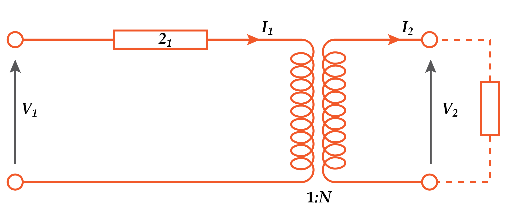
- Consider a single-phase transformer in which the total series impedance of the two windings referred to tl'ie primary is Z
- Then the p.u. impedance = I1Z1 / V1, where I1 and V1 are the rated or base values. The total impedance referred to the secondary = Z1N2
- and this in p.u. notation is
- = Z_1N^2 \left ( \frac{I_2}{V_2} \right )
- = Z_1N^2 \frac{I_1}{N} \cdot \frac{1}{V_1N} = \frac{Z_1N_1}{V_1}
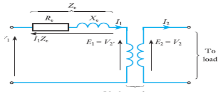
- Equivalent circuit of a single-phase transformer
-
- Hence the p.u. impedance of a transformer is the same whether considered from the primary or the secondary side. But expression (2.3) shows that Zp.u. is directly proportional to the base VA and inversely proportional to the base voltage squared. Although the VA rating of a transformer is independent of the side to which it refers, the voltage rating is different.
- Consequently if we wish to vary the voltage base dependent upon which part of the network to which we are referring, so that all voltages are around 1 p.u., we must recalculate the corresponding value of Zp.u.., as follows:
- Z_{p.u.} \left ( new ~ base\right) = Z_{p.u.} \left ( original~base \right) \times \left ( \frac{baseV_{old}}{baseV_{new}} \right)^2 \qquad \qquad (2.4)
- Note that the VA base is unchanged. If we wish to calculate Zp.u. to a new VA base, then
- Z_{p.u.} \left (new~base \right) \times \left (\frac {baseVA_{new}}{baseVA_{old}} \right) \qquad \qquad \qquad \qquad \qquad \qquad \quad(2.5)
Example
- In the network below, two single-phase transformers supply a 10 kVA resistance load at 200 V. Show that the p.u. load is the same for each part of the circuit and calculate the voltage at point D.
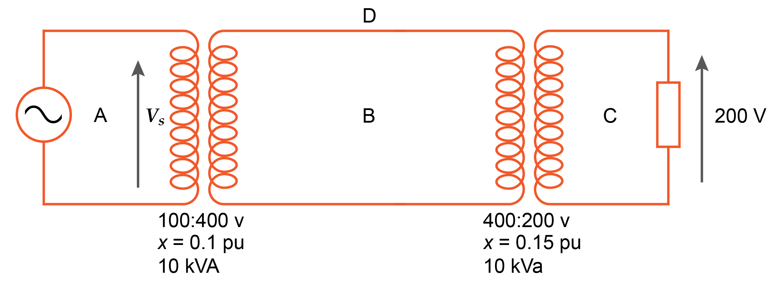
-
Faults in a power System
- There are five types of fault which can arise in a three-phase system:
- 1. a single line connected directly to earth;
- 2. two lines connected directly to earth;
- 3. all three lines connected directly to earth;
- 4. two lines connected directly to one another;
- 5. all three lines connected directly to one another.
- The first of these is the most common but the last is the most serious since it involves the greatest fault current (and fault V A) which has to be interrupted by a circuit breaker. It should be noted that in large power systems, fault currents are often many thousands of amperes.
- When a fault occurs, it is essential that it be detected and swiftly interrupted by the circuit breakers. Often the interruption is achieved in less than a tenth of a second. If such faults are not interrupted, the currents can severely damage power system equipment.
- Interruption of such large currents requires sophisticated circuit breaking equipment which must be sized appropriately so switchgear is designed and rated according to the apparent power or current which it is to break.
- As has already been indicated, a symmetrical three-phase fault, one in which the currents are equal in magnitude in each of the three phases, imposes the severest condition on circuits and circuit breakers. It is therefore most important to examine this condition. However, it is only necessary to examine one phase, other phases having identical fault current magnitudes.
Rules for per-unit calculations
- Rule 1: Choose a base V A value, SB, and use it throughout the calculation.
- Rule 2: Any per-unit impedance given for an actual equipment rating must be converted to the V A base chosen for the particular calculation.
- Z_{pu} = Z_{pu} \left ( actual\right ) \frac{S_B \left( Chosen\right )}{S_B \left ( actual \right)}
-
Terms and Concepts
- A balanced three-phase power system is one in which the currents in each of the three phases are equal. Balanced power systems can be simply and accurately, for many purposes, represented by a single- phase circuit incorporating transformer and line impedances.
- The network impedance has a considerable bearing on power system design and operation. It determines the voltage drop in current- carrying conductors. It also determines the short-circuit or fault current that will flow between generators and any fault location.
- Power system engineers use a per-unit method of calculation of voltage drops and fault currents. It simplifies such calculations in complex, interconnected networks operating at many different generation, transmission and distribution voltages.
- In the per-unit method, each value of current, voltage, impedance and apparent power (V A) is expressed as a fraction of its own nominal or rated value. A common base V A value, SB, is chosen and used throughout a per-unit calculation.
- A symmetrical three-phase fault, one in which the currents in each of the three phases are equal in magnitude, imposes the severest condition on circuits and circuit breakers. This situation can be represented by a single-phase circuit incorporating the network impedance between the source and the fault location.
- The value of the short-circuit or fault apparent power available at any location on the power system network, in the event of a fault at that location, is termed the fault level. The rating of switchgear must always exceed the fault level for the successful protection of power system equipment.
-
-
-
-