Wk 10 - A & B
Applications
- High velocity ratios with moderate size gears in a comparatively lesser space
- For example:
– Back gears of lathes– Differential gears of automobiles– Hoists– Pulley blocks– Wrist watches– Etc.
Epicyclic Gears
- Introduction
– Applications- Velocity Ratio
- Compound Gear Trains
- Solved Problems
Introduction
- Arm C Fixed
– Gear A or Gear B is driver of other gear- Gear A Fixed
– Gear B rotates upon (epi) and around (cyclic) Gear A
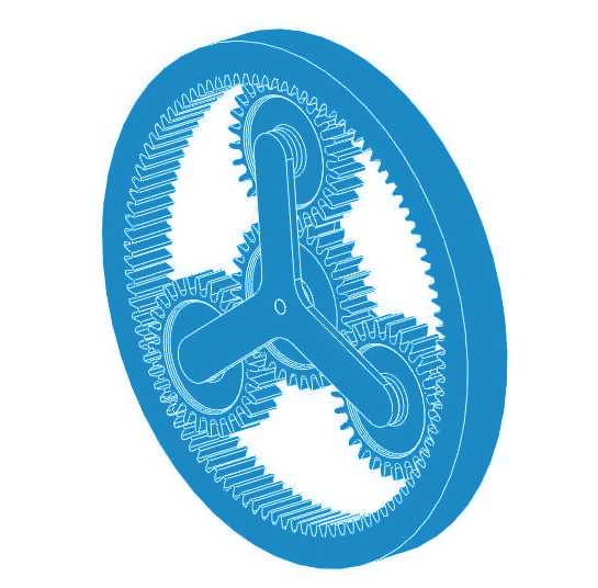
Compound Gear Train

- 📷 Compound Gear Train cross section - enlarge above image
- Co-axial shafts S1 and S2
- Annulus Gear A
– Internal Teeth- Compound Gear (Planet) B-C
– Carried by Arm and revolves freely on pin- Sun Gear D
– Co-axial with A and H but independent- Arm H
– When A is fixed, D provides the drive– When D is fixed, A provides the drive– H acts as a follower for both cases
Continues on next tab.
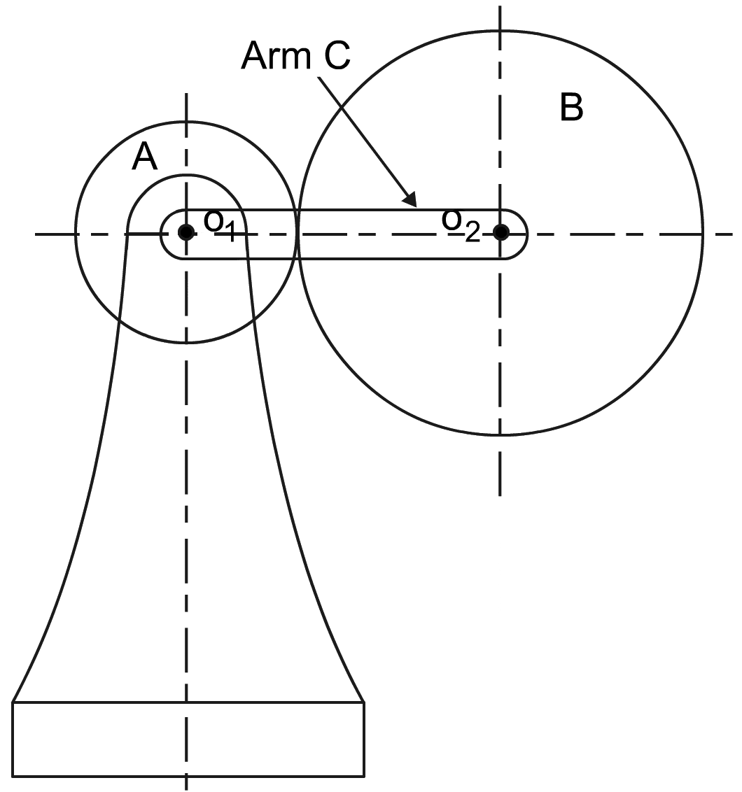
Velocity Ratio
- zA = number of teeth on Gear A
- zB = number of teeth on Gear B
- Assume Arm C, in the diagram above, is fixed
– Therefore axes of arms fixed relative to each other- Assume Arm C is fixed
– Therefore axes of arms fixed relative to each other, and:$$ \large \frac{N_B}{N_A} \; = \; \frac{z_A}{z_B} \quad Eqn.(5.1)$$– When A makes one revolution anticlockwise, B makes zA/zB revolutions clockwise- Assume anticlockwise is positive rotation and clockwise is negative rotation
- For Gear A making +1 revolutions, Gear B makes: $ \bigg( - \Large \frac{z_A}{z_B} \bigg) $ revolutions.
- 📷 Velocity Ratio Table
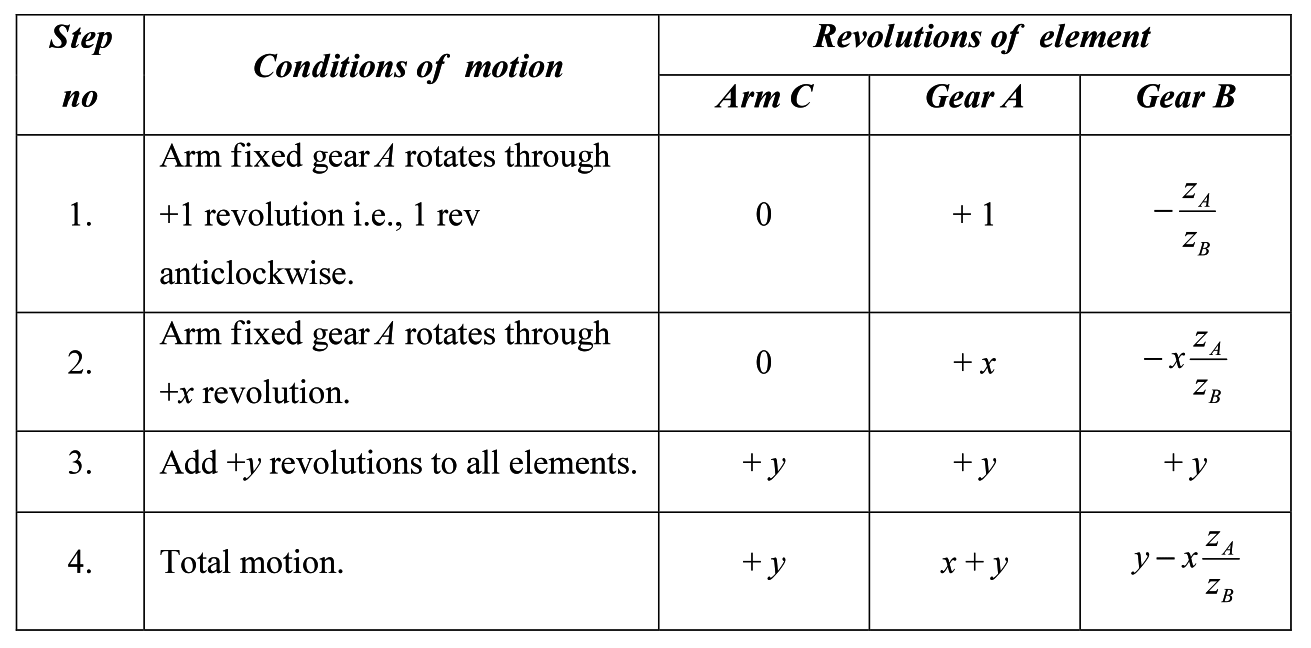
- The equations above can be used to generate the magnitude of the revolution value, but the directions must be taken from the following rules:
– Gears that mesh external teeth to external teeth rotate in opposite directions.– Gears that mesh external teeth to internal teeth rotate in the same direction.
- Velocity Ratio Table - Run Through Video
- Worked example 1 - Epicyclic Gears Video
- ⬇ Download worked example
Compound Gear Train (cont.)
- 📷 Compound Gear Train cross section - enlarge above image
- zA, zB, zC and zD number of teeth for each gear
- NA, NB, NC and ND speed of each gear
- When H is fixed, D is turned anti-clockwise, B-C and A rotate in clockwise direction
- From Equation (5.1) for ND = 1: $$ \large N_c = \frac{z_D}{z_C} \quad Eqn.(5.2) $$
- As B-C is a compound gear, NB = NC, and the next speed ratio to consider is NA/NB. Therefore; $$ \large \frac{N_A}{N_B} \; = \; \frac{z_B}{z_A} \quad Eqn.(5.3) $$
- Re-arranging for NA:
$$ \large N_A = N_B \times \frac{z_B}{z_A} \; \quad Eqn.(5.4) $$- Substituting the value for NB from Equation (5.2) (equal to NC):
$$ \large N_A = \frac{z_D}{z_C} \times \frac{z_B}{z_A} \quad Eqn.(5.5) $$ - The equations above can be used to generate the magnitude of the revolution value, but the directions must be taken from the following rules:
- Slope of thread($ \theta $)
- It is the inclination of the thread with the horizontal
Mathematically,- $$ \text{tan} \; \theta = \frac{Lead of screw}{Circumference of screw} = \frac{l}{ \pi D _{ms}} $$
$ l $ =lead of the screw = $ np $
$ p $ = pitch of the screw
$ D _{ms} $ = Mean diameter of the screw, and
$ n $ = number of start threads
- Derivation of the Angle of a Thread Equation Video
Design of Power Screws
- Introduction
- Nomenclature- Screw Jacks
- Torque Required- Efficiency- Overhauling and self-locking screws
Introduction
- Screws
- Made by cutting continuous helical groove on a cylindrical surface- External ThreadsCut on outer surface of a solid rod- Internal ThreadsCut on the inner surface of a hollow rod- V-ThreadsStronger and higher friction resistance than square threadsPrevent nut from slackeningUsed for bolts and nuts- Square ThreadsUsed for screw jacks, vice screws, etc.Nomenclature
- Helix
- Curve traced by particle moving along screw thread- Pitch
- Distance between screw threads- Lead
- Distance screw thread advances axially in one turn- Depth of Thread
- Distance between top and bottom surfaces of thread- Single-Threaded Screw
- Lead of the screw is equal to the pitch- Multi-Threaded Screw
- More than one thread is cut in one lead distance of a screw, e.g. double threaded screw has two threads cut in one length
Lead = Pitch $ \times $ Number of Threads- Slope of thread($ \theta $)
- (Cont.)
- Or with no collar bearing: $$ T = W \; tan \; ( \phi + \theta ) \frac{D _{ms}}{2} \quad \small \textbf{Eqn(6.3)} $$
- And to calculate the force P at the end of a lever length L to apply this torque: $$ T = W \; tan \; ( \phi + \theta ) \frac{D _{ms}}{2} + W \mu _c \frac{D _{mc}}{2} = P \times L $$
Screw Diameters
- Nominal Screw Diameter (DO)
- Also known as outside diameter or major diameter- Core Diameter (DC)
- Also known as outside diameter or major diameter- Mean Diameter (DM)
$$ D _{m} = \frac{D_o + D_c}{2} = D _o - \frac{p}{2} = D _c + \frac{p}{2} $$
- If the nominal and/or the core diameter are known:- Working Out the Mean Diameter of the Screw Video
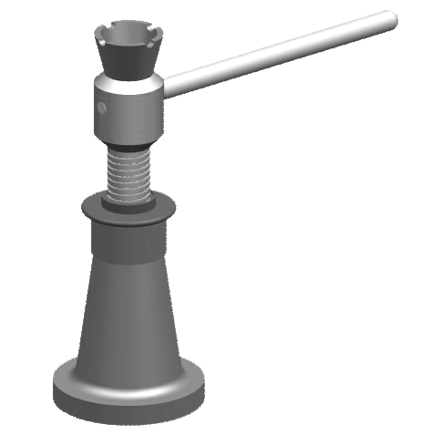
Screw Jack
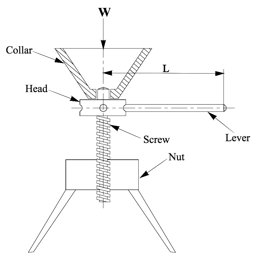 Screw jack with thrust collar
- Used to lift heavy loads by applying comparatively small effort at the handle
- Works on principle similar to inclined plane
- Load to be raised or lowered is placed on head of square threaded rod
- Square threaded rod rotated by application of force at end of the lever
Required Torque
- Torque required to lift the weight
Where:
$ p $ = pitch of the screw
$ D _{ms} $ = Mean diameter of the screw
$ D _{mc} $= Mean diameter of the collar
$ \theta $ = helix angle
$ W $ = load to be lifted
$ \mu _{s}$ = coefficient of friction of screw thread, i.e., between the screw and nut = tan $ \phi $ , where $ \phi $ is the friction angle
$ \mu _{c}$ = coefficient of friction of collar bearing
- Therefore
- A screw will always be self locking if:the friction angle is greater than the helix angle, orthe coefficient of friction is greater than the tangent of the helix angle
- Comparison of Thread Angle and Angle of Friction Video
- Worked Example 2 Introduction Video
- ⬇ Power Screws Nomenclature
- ⬇ Power Screws Worked Examples
Efficiency of a Screw Jack
- Efficiency defined as:
- Ratio between the ideal effort (neglecting friction) to the actual effort (taking friction into account- Remember:
$$ T = W \; tan \; ( \phi + \theta ) \frac{D _{ms}}{2} + W \mu _c \frac{D _{mc}}{2} \quad \small \textbf{Eqn(6.6)} $$
- For no friction, $ \mu _s $ = 0, therefore:
$$ T _0 = W \; \text{tan} \; \theta \frac{D _{ms}}{2} $$- Therefore, efficiency equation defined as: $$ \mu = \frac{T_0}{T} = \frac{W \; \text{tan} \; \theta \; \frac{\large D _{ms}}{2}}{W \; tan \; ( \phi + \theta ) \frac{\large D _{ms}}{2} + W \mu _c \frac{\large D _{mc}}{2}} $$
or for no collar bearing: $$ \eta = \frac{tan \; \theta}{tan \; (\theta + \phi)} $$
Overhauling and Self-Locking Screws
- Torque required to lower the load: $$ T = W \; tan \; ( \phi - \theta ) \frac{\large D _{ms}}{2} + W \mu _c \frac{\large D _{mc}}{2} $$
- If $ \phi $ < $ \theta $
- Torque required to lower the load may be negativeLoad moves down without application of torqueKnown as overhauling- If $ \phi $ > $ \theta $
- Torque required to lower the load will always be positiveEffort is required to lower the loadKnown as self-locking- Therefore