Wk 4
-

Thin Cylinders and Shells Under Internal Pressure
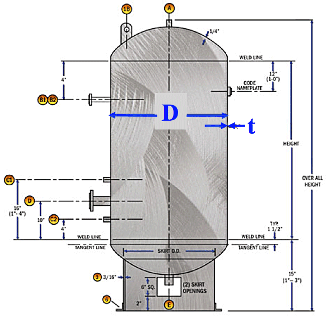
A cylinder is classified ‘thin’ if the ratio of wall thickness ‘t’ to outside diameter ‘D’ of the cylinder is < 1/20.
A thin-walled cylinder subjected to internal pressure produces three mutually perpendicular stresses, i.e.
i) circumferential or hoop stress
ii) radial stress
iii) longitudinal or axial stress. -
Hoop or Circumferential Stress $ \sigma _H $ or $ \sigma _\theta $
- Consider the half-cylinder shown in the figure, subjected to internal pressure p with an element of material highlighted showing the stresses set-up in the cylinder material.
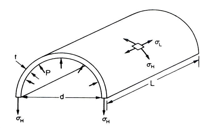
The stress set-up to resist the ‘bursting’ effect of the applied internal pressure is called the hoop or circumferential stress ($ \sigma _H $ or $ \sigma _\theta $).
Consider force equilibrium of the half-cylinder:
Total force on half-cylinder due to internal pressure = pressure $ \times $ projected area = p.d.L
Total resisting force due to hoop stress $ \sigma _H $ set-up in the cylinder wall = 2.$ \sigma _H $.L.t
∴ $ \sigma _H $.L.t = p.d.L
i.e.
$ \sigma _H = \large \frac{pd}{2t}$ (N/m2)
Thin Cylinders and Shells Under Internal Pressure
- When the ratio of wall thickness to outside diameter of the cylinder is < 1/20, it is assumed that the hoop and longitudinal stresses are constant across the cylinder wall thickness, and that the value of the radial stress set-up is small in comparison and can be neglected.
The initial assumptions are that the ends of the cylinder and any riveted joints have no effect on the stresses produced – in practice however, they will have an effect.
- Consider the half-cylinder shown in the figure, subjected to internal pressure p with an element of material highlighted showing the stresses set-up in the cylinder material.
-
- Change in Length (cont.)
Change in length = longitudinal strain $ \times $ original length
$\Delta L = \large \varepsilon _L . L = \frac{1}{E} [ \sigma _L - v \sigma _H] L $
$ \therefore \; \Delta L = \large \frac{pdL}{4tE} (1-2v) \; (m) $
- Change in Diameter:
Diametrical strain, $ \varepsilon _D $ = change in diameter/original diameter = $\Delta d/d= \varepsilon _H $
Change in circumference = diametrical strain $ \times $ original circumference $ = \varepsilon _H. \pi .d $
New circumference = $ \pi .d + \varepsilon _H. \pi .d = \pi .d(1+ \varepsilon _H) $
But this is the circumference of a circle of diameter $ d(1+ \varepsilon _H ) $.
Hence, the new diameter = $ d(1+ \varepsilon _H ) \therefore \; \Delta d = d (1 + \varepsilon _H ) - d = d. \varepsilon _H $:
$ \therefore \; \varepsilon _D \large \frac{d \varepsilon _H}{d} \normalsize = \varepsilon _H $
- The diametrical strain equals the circumferential or hoop strain, and hence the change in diameter is found from:
$$ \Delta d = d. \varepsilon_H = \frac{d}{E} \normalsize [\sigma_H - v \sigma_L] $$ $$i.e. \quad \Delta d = \frac{pd^2}{4tE} (2 - v) \; (m) $$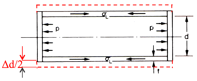
Longitudinal or Axial Stress $ ( \sigma L ) $
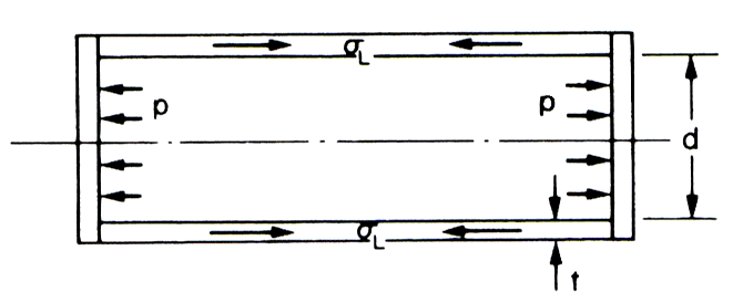
- Consider the view of the half-cylinder shown in the figure.
Considering force equilibrium of the half-cylinder:
Total force on the end of the cylinder due to internal pressure = pressure $ \times $ area = $ p . \large \frac{\pi d^2}{4} $
Total area resisting this force = $ \pi $.d.t (approx.)
∴ Stress set-up = $ \; \frac{Force}{Area} = \large \frac{p . \pi d^2}{4 \pi d t} $
i.e. $ \quad \; \sigma_L = \large \frac{pd}{4t} \normalsize (N/m^2) $Changes in Dimensions
- Change in Length:
Longitudinal strain = $\large \varepsilon _L \normalsize = \large \frac{1}{E} [ \sigma _L - v \sigma _H] $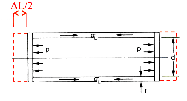
- Change in Length (cont.)
-
- Total resisting force due to hoop stress σH set-up in the cylinder wall = $ \sigma_H .\pi .d.t $
$ \therefore \; p . \large \frac{\pi d^2}{4} \normalsize = \sigma_H . \pi.d.t $
i.e.$ \quad \sigma_H = \large\frac{pd}{4t} \normalsize (N/m^2) $
- Changes in Dimensions
Change in Volume:
Change in volume $ \Delta V $ = volumetric strain $ \times $ original volume = $ \varepsilon _V . \; V $
Volumetric strain = sum of three mutually perpendicular strains (in this case all equal) = $$ 3 \varepsilon _D - 3 \varepsilon _H = \frac{3}{E} [\sigma _H - V \sigma _L ]$$ $$ i.e. \quad \Delta V = \frac{3pdV}{4tE} (1 - v ) \; (m^3)$$
- Change in Volume:
Change in volume $\Delta V $ = volumetric strain $ \times $ original volume = $ \varepsilon_V . \; V$
$ \therefore \; \; \varepsilon_v = \varepsilon_x \times \; \varepsilon_y \times \; \varepsilon_z $
(in the case of a cylinder $ = \varepsilon_L +2 \; \varepsilon_D )$
$ \therefore \; \; \varepsilon_v = \varepsilon_L +2 \; \varepsilon_D $
$ = \frac{1}{E} [\sigma_L - v \sigma_H] $
$ + \frac{2}{E} [\sigma_H - v \sigma_L] $
$ = \frac{pd}{4tE} (5 - 4v) $
$ i.e. \quad \Delta V = \large \frac{pdV}{4tE} (5 - 4v) \; (m^3) $
- Thin Spherical Spheres under Internal Pressure
The symmetry of the sphere sets up stresses due to internal pressure and these will be mutually perpendicular circumferential or hoop stresses of equal value, and a radial stress (again assumed negligible for thin wall material). The stress system is therefore an equal biaxial hoop stress. (see the diagram in the top right collumn)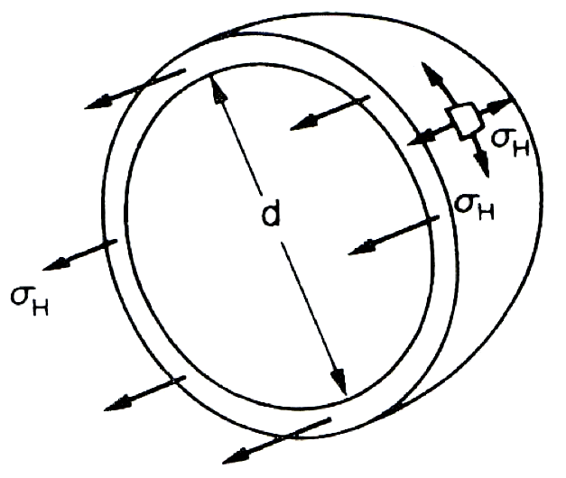 Consider the equilibrium of the half-sphere shown in the figure.
Total force on half-sphere due to internal pressure = pressure $ \times $ projected area: $= p . \large \frac{\pi d^2}{4} $ - Total resisting force due to hoop stress σH set-up in the cylinder wall = $ \sigma_H .\pi .d.t $
-
2D Stress Analysis
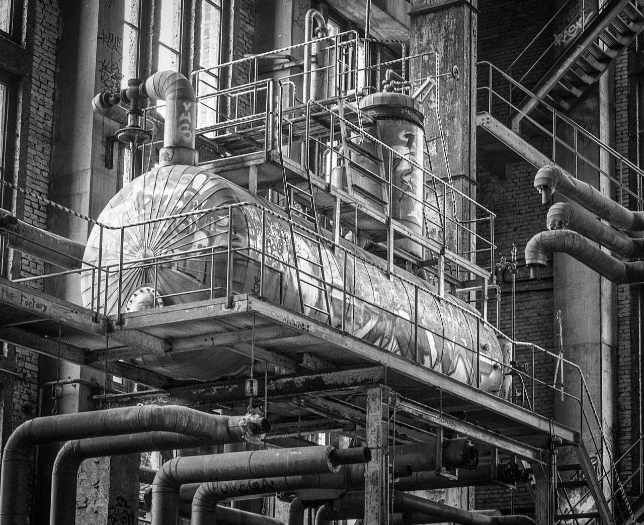
- A 2D Stress Analysis application – an Air Receiver/Pressure Vessel/Thin Cylinder
– Please view the video below. When finished move to the next tab.
Continues on next tab
Thin Rotating Cylinders
- Rotating thin cylinders are commonly found in various processing industries and are worthy of consideration with regards to stress states created by centrifugal force effects. Consider the thin cylinder (or ‘ring’ for very short lengths) shown in the figure which is subjected to a radial pressure p caused by the centrifugal effect of its own rotating mass.
The centrifugal effect on a unit length of the circumference is: $ p = m \omega^2 r $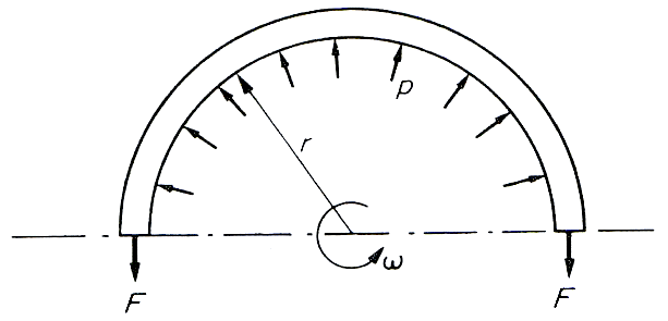
Now, considering equilibrium of the half-cylinder: $ 2F = p.2r $ or $ F = p.r $ where F is the circumferential or hoop tension set-up due to rotation. $$ \therefore \; \; F = p.r = m \omega ^2r^2 $$ This tension is transmitted through the complete circumference and is therefore restricted by the complete cross-sectional area: $$ \small \text{ Hoop stress,} \; \normalsize \sigma_H = \frac{F}{A} =\frac{m \omega^2r^2}{A} $$ where $ A $ is the cross-sectional area of the cylinder or ring.
Now, with unit length assumed, $ m/A $ is the mass of the cylinder/ring material per unit volume, i.e. the density $ \rho $: $$ \text i.e. \quad \normalsize \sigma_H = \rho \omega^2r^2 \; \; (N/m^2) $$- ⬇ Download worked example
-
- (Cont.)
- 📷 sin2θ, cos2θ can be substituted into Eqns to give $ \sigma _{\theta max}$ and $ \tau _{\theta max}$: seen here
(Eqns 1 & 2 are shown in the video on tab 4.4).
The larger value of $ \sigma _\theta $ is termed the major principal stress $ \sigma _1 $, i.e.,
$ \quad \sigma _1 = \frac{\sigma _x + \sigma _y }{2} + \sqrt{\Bigg( \frac{ \sigma _x - \sigma _y }{2} \Bigg)^2 + \tau^2} \quad \small Eqn.(4) $
- The smaller value of $ \sigma _\theta $ is termed the minor principal stress $ \sigma _2 $, i.e.,
$ \quad \sigma _2 = \frac{\sigma _x + \sigma _y }{2} - \sqrt{\Bigg( \frac{ \sigma _x - \sigma _y }{2} \Bigg)^2 + \tau^2} \quad \small Eqn.(5) $
- These planes ($ \sigma _1 $ and $ \sigma _2 $) are inclined at an angle $ \theta $ to the plane carrying $ \sigma_x $ as given by Eq(3):
$$ \text{tan} \; 2 \theta = \frac{2 \tau}{\sigma _x - \sigma _y} $$- Similarly it can be shown that the maximum shear stress $ \tau_{max}$ is:
$ \tau_{max} = \sqrt{\Bigg( \frac{ \sigma _x - \sigma _y }{2} \Bigg)^2 + \tau^2} \quad \small Eqn.(6) $
- It can also be shown that:
$$ \tau _{max} = \frac{\sigma _1 - \sigma _2}{2} \quad \small Eqn.(7)$$- The equations for $ \sigma _1 , \sigma _2 , \sigma _\theta , \tau_{max} $ are equations that describe a circle having $ \tau $ as its ordinate (y-axis) and $ \sigma $ as the abscissa (x-axis).
This is known as the Mohr’s Circle of Stress and allows for a graphical solution of 2D stress system problems.
⬇ Graphical (Mohr Circle) Solution: Worked Example
⬇ 2D Stress Analysis: Worked Example
⬇ 2D Stress Analysis - Analytical: Worked Example
$ \sigma _{\theta _{max}} = \large \frac{\sigma _x + \sigma _y }{2} + \frac{\sigma _x + \sigma _y }{2} \Bigg[ \frac{\sigma _x + \sigma _y }{\sqrt{(\sigma_x - \sigma_y)^2 + 4 \tau^2}}\Bigg] + \Bigg[ \frac{2 \tau^2}{\sqrt{(\sigma_x - \sigma_y)^2 + 4 \tau^2}}\Bigg] $
$ = \large \frac{\sigma _x + \sigma _y }{2} + \frac{1}{2} \Bigg[ \frac{( \sigma _x + \sigma _y)^2 + 4 \tau^2 }{\sqrt{(\sigma_x - \sigma_y)^2 + 4 \tau^2}}\Bigg] $
$ = \frac{1}{2} \Bigg[ ( \sigma _x + \sigma _y) \pm \sqrt{(\sigma_x - \sigma_y)^2 + 4 \tau^2} \Bigg] $
$ \text{or} \quad \sigma _{\theta _{max}} = \large \frac{\sigma _x + \sigma _y }{2} \pm \sqrt{\Bigg( \frac{ \sigma _x - \sigma _y }{2} \Bigg)^2 + \tau^2}$
2D Stress Analysis (cont.)
For the maximum values: $$ \frac{d\sigma _\theta }{d \theta} = \frac{d \tau _\theta}{d \theta} = 0 $$
$$ \therefore \; \frac{d \tau _\theta}{d \theta} = \frac{d}{d \theta} [ \frac{\sigma _x - \sigma _y}{2} sin \; 2 \theta - \tau \; cos \; 2 \theta] = 0 $$
$$ \therefore \; \frac{d \tau _\theta}{d \theta} = - \bigg( \frac{\sigma _x - \sigma _y}{2} \bigg) 2 \; sin \; 2 \theta + 2 \tau \; cos \; 2 \theta] = 0 $$
$ \text{or} $ $$ \text{tan} \; 2 \theta = \frac{2 \tau}{\sigma _x - \sigma _y} \quad \small Eqn.(3)$$- Using Eq(3 - above), the following diagram is useful:
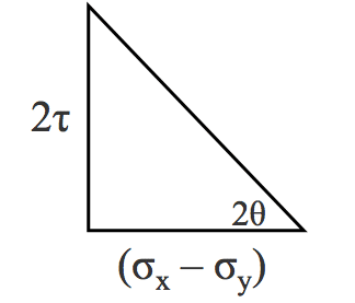 $$ \sqrt{(\sigma_x - \sigma_y)^2 + 4 \tau^2} $$
$$ \therefore \; \quad sin \; 2 \theta = \frac{2 \tau}{\sqrt{(\sigma_x - \sigma_y)^2 + 4 \tau^2}} $$
$ \text{and} $ $$ \quad cos \; 2 \theta = \large \frac{\sigma_x - \sigma_y}{\sqrt{(\sigma_x - \sigma_y)^2 + 4 \tau^2}} $$ - (Cont.)
-
-