Wk 3
Combined Bending & Direct Stress
This week, two very important topics are presented. The first topic is ‘Combined Bending & Direct Stress’ which brings together 2 stresses learned in Mechanical Principles A – Direct Stress (load/area, tensile or compressive) and Bending Stress (tensile and compressive).
It will be shown that these 2 effects when acting simultaneously on a component or structure can be added together algebraically using the principle of superposition. The second topic is Torsion which is the study of circular shafts being subjected to a twisting action called torque or torsion. This twisting causes torsional shear stress to act within the shaft material and this has to be calculated to ensure the safe operation of shafts.
- Combined Bending and Direct Stress of a Loaded Column
A short concrete column is loaded in compression by a concentrated load W at point A on the axis of symmetry, at a distance ‘e’ from the centroid G of the cross-section as shown in Figure 2.
It is required to find the maximum eccentricity ‘e’ of the load if there is to be no tensile stress in the concrete and to obtain the value for a rectangular section.Figure 2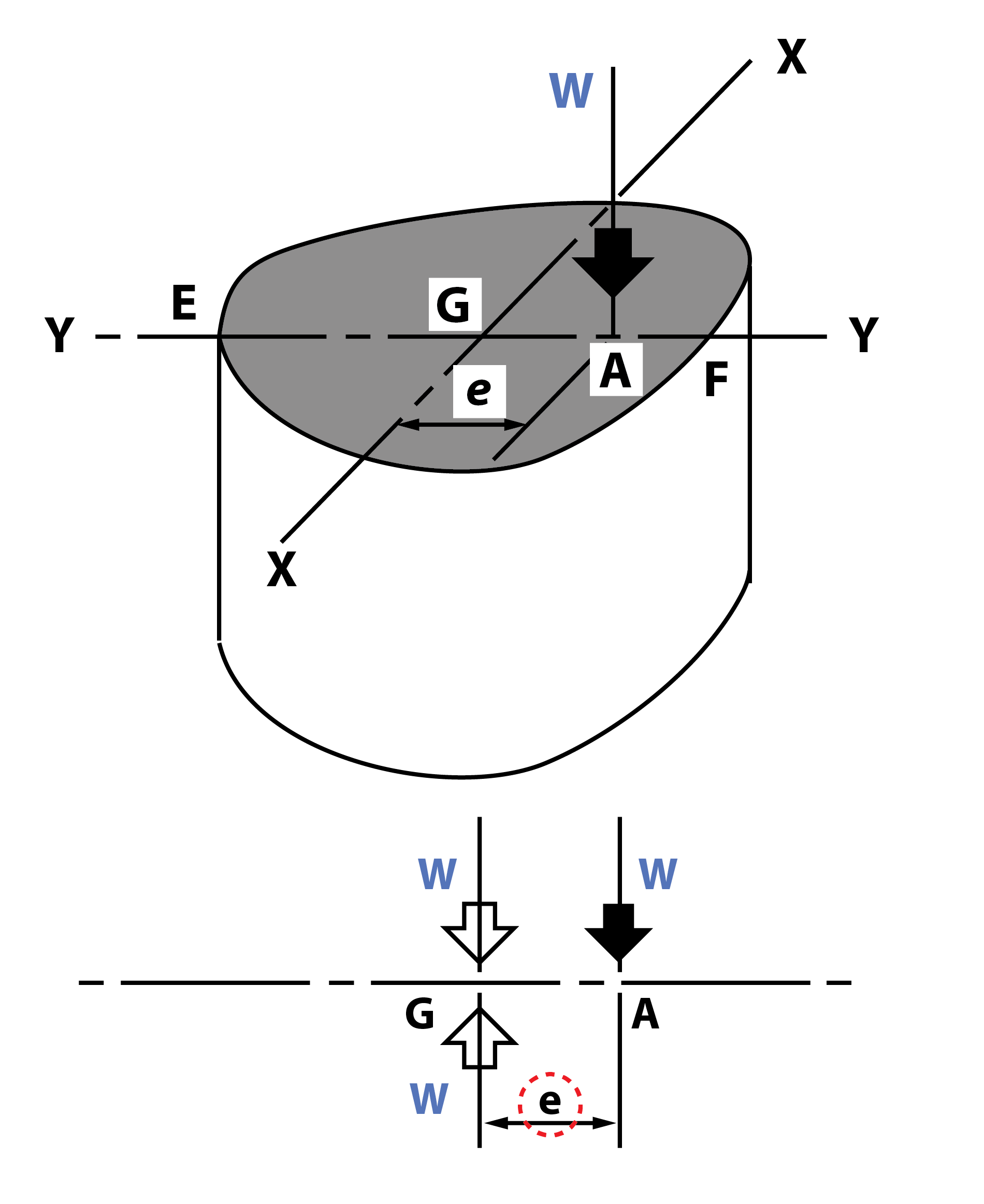 The moment applied to the column is the moment of the load about an axis through the centroid. Thus the eccentric load W may be replaced by:
(a) a compressive load W at the centroid G;
(b) a couple or bending moment M = W . e about the axis X-X through the centroid G.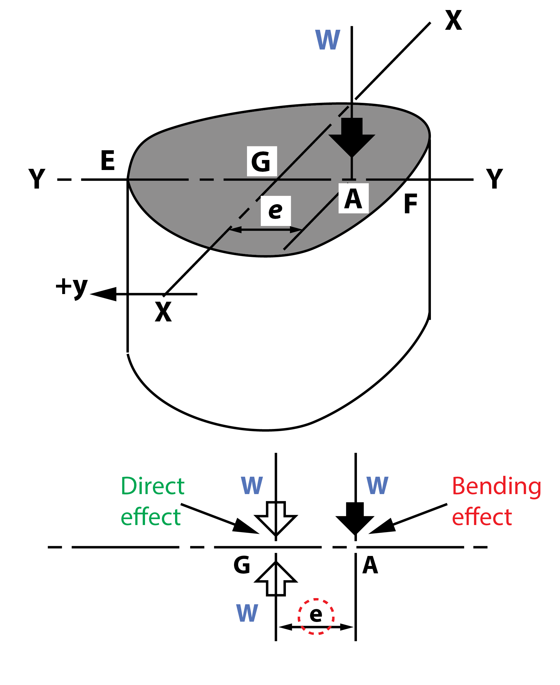 Let A be the area of section, I the second moment of area about X-X, y the distance of any point in the plane of the section from X-X:
$ Direct \; compressive \; stress = - \frac{W}{A}$
$ Bending \; stress = - \frac{M}{I} y $
(Note: tensile in EG when y is positive, compressive in GF when y is negative)
Hence, the total stress at any point distance y from X-X $$ = - \frac{W}{A} \; + \; \frac{W.e}{I} y_1 $$
Combined Bending & Direct Stress
- Principle of Superposition
The stress at any point of a structure, beam or strut carrying several loads may be found by considering each load separately as if it acted alone. The total stress is then the algebraic sum of the stresses due to each separate load. This is the method of superposition.
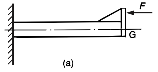
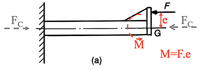
A particular case is that of combined bending and direct stress due to a single load. The cantilever shown in Figure 1(a), is subject to the axial load F offset from the centroid (G) of the cross section.
Figure 1 a
This produces two effects:
(a) a simple compression;
(b) a bending moment (M = F x e) about an axis through G.
The stress due to each effect (direct compressive stress -$ \sigma _d$ and bending stress ±$ \sigma _b$) may be calculated separately and added to give the total stress. The method of superposition does not apply if one load alters the character or effect of another.
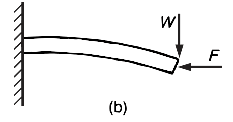
For example, the cantilever shown in Figure 1(b) is subjected to an axial load F and a transverse load W. The cantilever may deflect sufficiently under the transverse load so as to increase the moment due to F. Only when this deflection is negligible does the principle of superposition apply.
Figure 1 b
- Combined Bending and Direct Stress of a Loaded Column
(Cont.)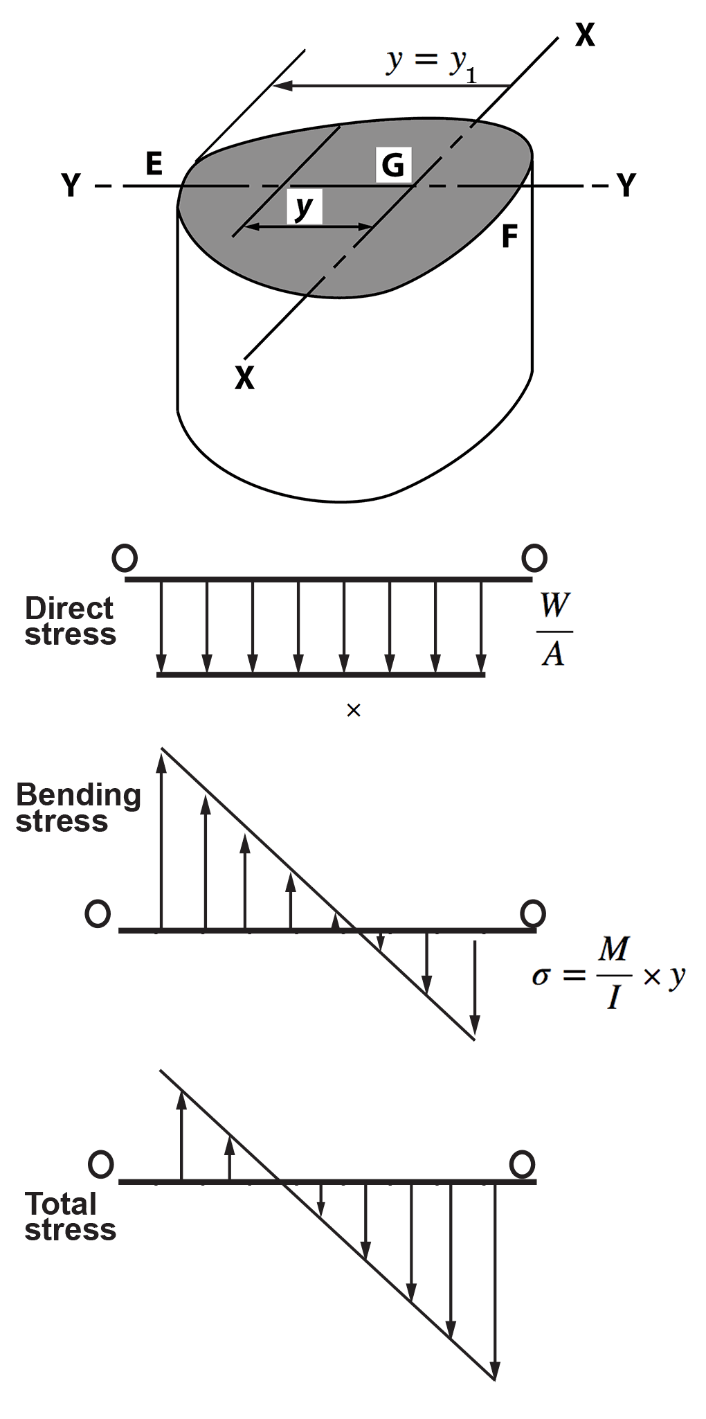 Now M = W . e and at E, y = y1:
Stress at E = - $ \large \frac{W}{A} \; \normalsize + \large \; \frac{W . e}{I} \normalsize \; y_1 = 0 $ (for no tensile stress)
Hence: $ \quad \large \frac{W e y_1}{I} = \frac{W}{A} \quad $ i.e. $ \; e = \large \frac{I}{Ay_1}$
For a rectangular section, breadth $ b $, depth $ d $, A = $ bd $, $ I = bd ^3 $/12 and $ y_1 $ = ½ $ d $, then:
$ e = \large \frac{bd^3/12}{bd \; \times \; ½ \; d} $ i.e., $ e = \large \frac{d}{6} $
Thus for no tension in a rectangular section, the load must act at or within a distance of $ d/6 $ from the centroid. This is known as the middle-third rule.
- ⬇ Download worked example
Combined Bending and Direct Stress of a Loaded Column (contd.)
- Figure 3 shows the variation of direct, bending and total stress across the section.
Figure 3
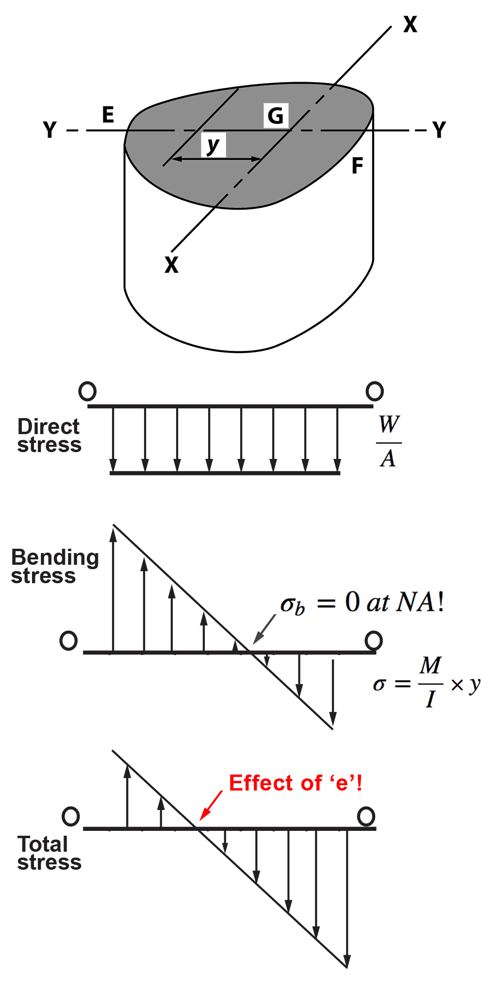
In the above figure 3, the effect of the eccentricity of loading is that the line of zero stress (neutral axis) is shifted to the left of the centroid.
The form of the total stress diagram depends on the magnitudes of the direct and bending stresses.
The maximum tensile stress is at E - for no tension at any point the stress at E must = 0.- Twisting of Circular Shafts
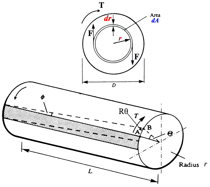
To derive the relation between torque T, angle of twist and shear stress for a solid shaft of diameter d,(radius r), we make the following assumptions:-
• The shaft is composed of a succession of thin concentric tubes.
• Each thin tube carries shear force independent of, and without interfering with, its neighbours.
• Lines which are radial before twisting are assumed to remain radial after twisting.
• The shaft material is not stressed beyond the elastic limit.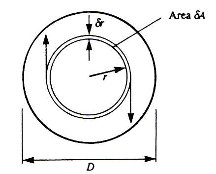 For any elemental thin tube of thickness d$r$ at radius $ r $ as shown in Figure 5,
elemental area of section dA = 2$ \pi $r .dr
For any elemental thin tube of thickness d$r$ at radius $ r $ as shown in Figure 5,
elemental area of section dA = 2$ \pi $r .dr
Now, shear stress, $ \tau = \large \frac{F}{A} $ or, F = A.$ \tau $
If $ \tau $ is the shear stress at radius $ r $, then shear force on tube F = A. $ \tau $ = 2$ \pi $r dr. $ \tau $
Thus, the torque carried by the tube:
T = F.r = (2$\pi$r$\tau$dr).r = 2$\pi$r$^2 \tau $.dr $ \quad \normalsize Eqn.(3)$
Figure 5
 Continues on next tab.
Theory of Torsion
- Examples of systems subjected to ‘torsion’ (or ‘twisting’) can be seen below:
 Click to replay above animation
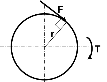
- Torque
Torque is defined as the turning or twisting effect of a force about a point around which it rotates. Referring to Figure 4, the torque $ T $ produced by the tangentially acting force $ F $ is the product of the force and the radius $ r $ at the point of force application, i.e.
$ \textit {'Static Torque'} \\ \large T = F.r \quad (Nm) \quad \quad \normalsize Eqn.(1)$Figure 4
- Torque and Power
Recall the Dynamics - Angular Motion and Torque: if a shaft rotates at speed of N (rev/min) due to the effect of a torque T (Nm), then the power P (W) transmitted by the shaft is given by:or
Power = work done by torque per second = torque $ \times $ angular speed i.e
$P = T. \omega $ [where $ \omega = \large \frac{2 \pi N}{60}$ (rad/s)]
$ \quad \normalsize \textit {'Dynamic Torque'} \\ \quad P = \large\frac{2 \pi NT}{60} \normalsize (W) \quad \quad \small Eqn.(2)$- Twisting of Circular Shafts
- Since radial lines before twisting remain radial after twisting, then $ \theta $ is the same for all the thin tubes making up the shaft. Also G and L are constant, and therefore:
$$ T = \frac{G \theta}{L} \int_{0}^{d/2} 2 \pi r ^3 dr = \frac{G \theta}{L} J \quad Eqn.(6) $$ Where $$ \int_{0}^{d/2} 2 \pi r ^3 dr = \quad J = \frac{\pi d^4}{32} $$ J is the polar second moment of area of a shaft of circular section. The units of J are m4 or mm4.
Then, rearranging Eqn.(6) gives: $$ \frac{T}{J} = \frac{G \theta}{L} $$ and, using Eqn.(3) - seen on tab 1.3: $$\scriptsize Theory \; of \; Torsion \; Equation \\ \normalsize \frac{T}{J} = \frac{\tau}{r} = \frac{G \theta}{L} \quad \small Eqn.(7) $$ Other useful arrangements of Eqn.(7) are as follows: $$ r =\frac{Tr}{J} \small \quad Eqn.(8)$$ $$ \text {and} \\ \\ \theta =\frac{TL}{GJ} \small \quad Eqn.(9) $$ Some important points should be noted:
1. The angle of twist $ \theta $ varies directly with length L.
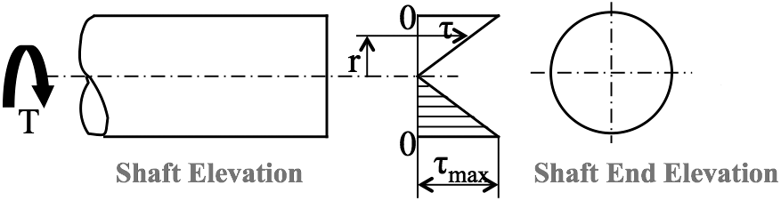
2. Since $ \tau $ = Tr/J, then for a given torque T, the shear stress $ \tau $ is proportional to the radius r. Thus the maximum shear stress occurs at the outside surface where r = d/2, and the shear stress at the centre of the shaft is zero.
Figure 6 shows the variation of $ \tau $ across a diameter.
Figure 6
Theory of Torsion (cont.)
- Twisting of Circular Shafts
Figure 5
Note:
From a torsion test: Shear stress/shear strain = $ \tau /γ $ = G, or, $ \tau $ = G $ γ $
where $ γ $ = r$ \theta $ /Land G = modulus of rigidity
If $ \theta $ is the angle of twist of the tube in a length L, then the shear stress is given by: $$ \tau = \frac{G \theta}{L} \normalsize r \quad \quad \normalsize Eqn.(4) $$ and, from Eqns.(3) and (4) above, and on the previous tab (1.3): torque carried by tube T = F.r,
i.e. T = 2$\pi r^2 \tau dr$ = 2 $\pi r^2 \times \large \frac{G \theta}{L} \normalsize r \times \; dr $
= 2$ \pi \times \large \frac{G \theta}{L} \normalsize r^3 \times dr \quad \quad Eqn.(5)$
The whole torque $ T $ carried by the solid shaft is the sum of all the elemental torques, i.e. $$ T = \int_{0}^{d/2} 2 \pi \frac{G \theta}{L} .r^3dr $$- Since radial lines before twisting remain radial after twisting, then $ \theta $ is the same for all the thin tubes making up the shaft. Also G and L are constant, and therefore:
Stiffness and Strength
- The stiffness or torsional rigidity of a shaft is the torque to produce unit angle of twist. Thus if a torque $ \textit T $ produces a twist $ \theta $ then:
$$ stiffness = \frac{T}{\theta} \; = \; \frac{GJ}{L} (Nm/rad) \quad \; Eqn.(10) $$ The strength of a shaft is measured by the torque it can transmit for a given permissible value of the maximum shear stress.
For a given shear stress therefore the strengths of two shafts are in the ratio of the corresponding torques.
Alternatively, for a given torque, the strengths are in the ratio of the maximum allowable shear stresses produced.
- ⬇ Download worked example
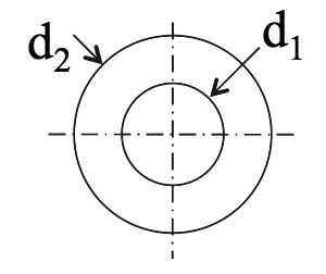
Twisting of Hollow Shaft
- If $ d_2 \; \text{and} \; d_1 $ are the outside and inside diameters of a hollow shaft subject to a twisting moment $ \textbf T $, then Eqn.(6) - seen on tab 1.4 becomes:
 $$ T = \frac{G \theta}{L} \int_{d_1/2}^{d_2/2} 2 \pi r ^3 dr = \frac{G \theta}{L} J $$
and, as before, we have:
$$ J= \int_{d_1/2}^{d_2/2} 2 \pi r ^3 dr = $$
$$ T = \frac{G \theta}{L} \int_{d_1/2}^{d_2/2} 2 \pi r ^3 dr = \frac{G \theta}{L} J $$
and, as before, we have:
$$ J= \int_{d_1/2}^{d_2/2} 2 \pi r ^3 dr = $$
$$ \\ J = \frac{\pi(d^4_2 - d^4_1)}{32} \\ \small Polar \; 2nd \; moment \; of \\ Area \; for \; a \; hollow \; shaft $$ Since, from Eqn.(7) - seen on tab 1.4 $ \tau = \large\frac{T.r}{J} $ the maximum shear stress for a given torque is again at the outside fibres of the shaft, where $ r = d_2/2$
Note: For a very thin tube of thickness $ t $, mean radius $ r $ :
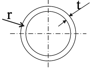 $ J $ = area of section $ .r^2 $ = 2 $\pi rt \; .r^2 = 2\pi r^3t $
and substituting for J in Eqn.(6): $$ T = \frac{T}{2\pi r^3t} = \frac{\tau}{r} = \frac{G \theta}{L} $$- The stiffness or torsional rigidity of a shaft is the torque to produce unit angle of twist. Thus if a torque $ \textit T $ produces a twist $ \theta $ then:
-
Summary
⬇ Combined Bending & Direct Stresses Summary
⬇ EDA2 Torsion Summary -
Tutorials
- ⬇ Combined Bending & Direct Stresses tutorial
- ⬇ Torsion tutorial