Wk 8
Free Damped Vibration Introduction
This week, 2 topics will be presented - Free Damped Vibration and the Design of Helical Compression Springs. Free Damped Vibration continues the work of Mechanical Principles A where Free Undamped Vibration was studied and natural frequencies were calculated for a spring/mass systems. Here, we will look at mass/spring systems again but with the addition of dampers to control vibration and enable us to calculate vibration amplitudes by considering the level of damping in the system. The Design of Helical Compression Springs topic will show you how to design many of the features of these types of springs including the mean coil diameter, the wire diameter, spring deflection or compression, the torsional shear stress in the spring material, the free length, the solid length amongst several other features.
Damped Free Vibration Lecture Videos
- Damped Free Vibration Video Lecture - Part One
- Damped Free Vibration Video Lecture - Part Two
- ⬇ Damped Free Vibration Worked Example 1 & 2
Helical tension and compression springs are in the former category; helical torsion and plate springs are in the latter.
In every case the spring performs its function by being deformed by external loading, the work done being stored in the form of strain energy.
Subsequently the spring is allowed to return to its original form, and in doing so, it gives up its stored energy.
The main properties of a spring of interest to the designer are:
capacity for absorption of energy
deformation produced by applied force
resonant frequency of vibration…….amongst many others!
Design of Helical Springs Introduction
The principal purpose of any spring is to absorb energy and then to release it under controlled conditions.
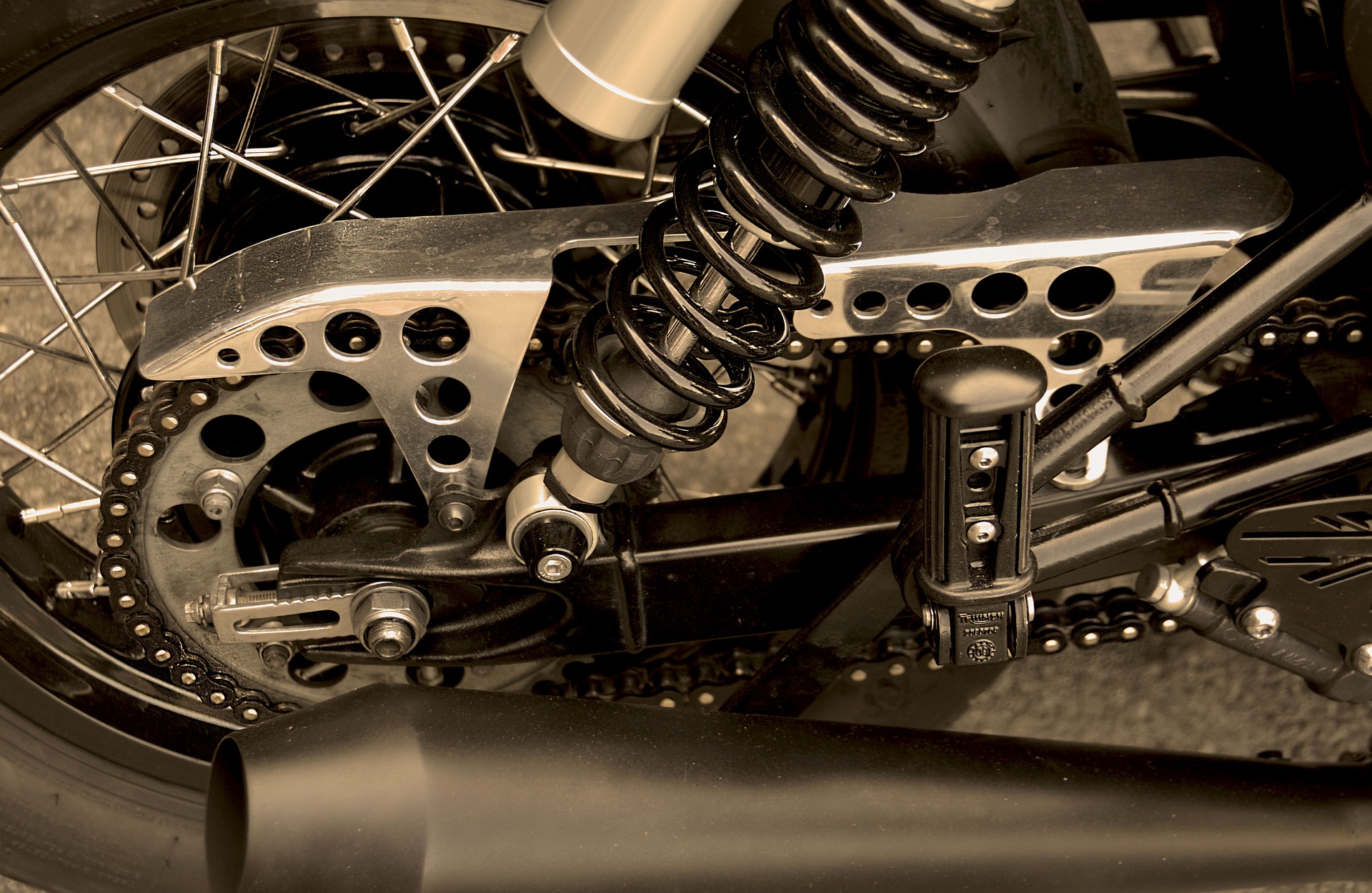
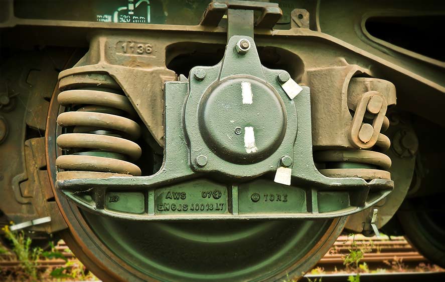
A spring may be used as a driving force as, e.g., in watch mechanisms, clockwork toys, etc., or as a balancing medium e.g., the mechanism for supporting the boot lid of a car, or stabilising a pivotal desk lamp, etc., or it may be used to absorb the shock of collision as in the suspension of a car, or the buffers of railway rolling stock.
Generally, they are used in mechanical machine design to cushion impact and shock loading, to store energy, to maintain contact between members, for force measuring devices, to control vibration, and many other related functions.
Wherever they are used, springs are almost certain to be subjected to arduous duty, where any failure may result in severe damage to the mechanisms in which they function.
Springs are susceptible to overstressing and to the effects of fatigue, and it is essential that they be properly designed to perform the selected task.
It is not accepted practice to select a spring at random from a raised collection and apply it to an application without first checking its proper suitability.
Springs are divided into two main categories – those subjected primarily to torsional stresses and those subjected to bending stresses.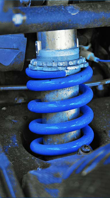
Springs can be made from a variety of materials - individual choice may be governed by factors such as cost, stress requirements, non-magnetic properties, corrosion resistance, freedom from electrolytic effects, weight, etc.
The following table gives values of Torsional Modulus of Elasticity, G (or ‘Rigidity’) for the most frequently used spring materials, in GN/m2:
Carbon Steel 80
Monel 62
Beryllium Copper 45
Phosphor Bronze 43
Spring Design involves a relationship between:
force (N)
torque (Nm)
deflection (m)
stress (N/m2)
Design of Helical Tension and Compression Springs
- These springs are formed of wire usually, but not necessarily, of solid circular section, wound on a former of cylindrical or conical shape.
It should be noted that modern CNC controlled high speed autocoiling spring making machines do not use formers, but achieve the required form by passing the wire through contoured guides, often at very high temperatures.
When adjacent coils of the spring are in contact under no load conditions, the spring absorbs energy by being compressed under external load, and it is known as a compression spring. The material of such springs are subjected, under load, primarily to torsional stresses. A similar scenario exists for springs which are tensioned under external loading.
- 📷 Figure 1 shows typical tension and compression springs with standard nomenclature.
- A well-designed compression spring can be repeatedly compressed solid without the safe stress in the material being exceeded.
In the case of a tension spring, however, there is no automatic limit to its deflection and so it is essential to ensure that the spring material is not accidentally overstressed in service.
It is usual to specify values of maximum load and deflection which are significantly lower than those for equivalent compression springs.
However, where possible, it is always desirable to arrange constraints in the movement of a mechanism employing a tension spring so that accidental overstretching is prevented.
- These springs are formed of wire usually, but not necessarily, of solid circular section, wound on a former of cylindrical or conical shape.
- (Cont.)
where, $ \tau $ = total torsional shear stress (N/m2),
F = axial load (N),
D = mean diameter of coil (m),
d = diameter of wire (m),
C = spring index of wire = D/d,*1
and, K = Wahl Factor*2
*Note 1: C > 5, typically between 5 – 12. If C < 5 then forming can be difficult, with the possibility of cracks forming in the wire.
*Note 2: There are several functions available for the Wahl Factor K (in terms of spring index C), the most common being: $$ \large K = \frac{4C - 1}{4C - 4} + \frac{0.615}{C} $$- 📷 Figure 3 shows a plot of the above Wahl Factor K v. Spring Index C. - seen larger here
Figure 3: Wahl Factor vs. Spring Index for Round Wire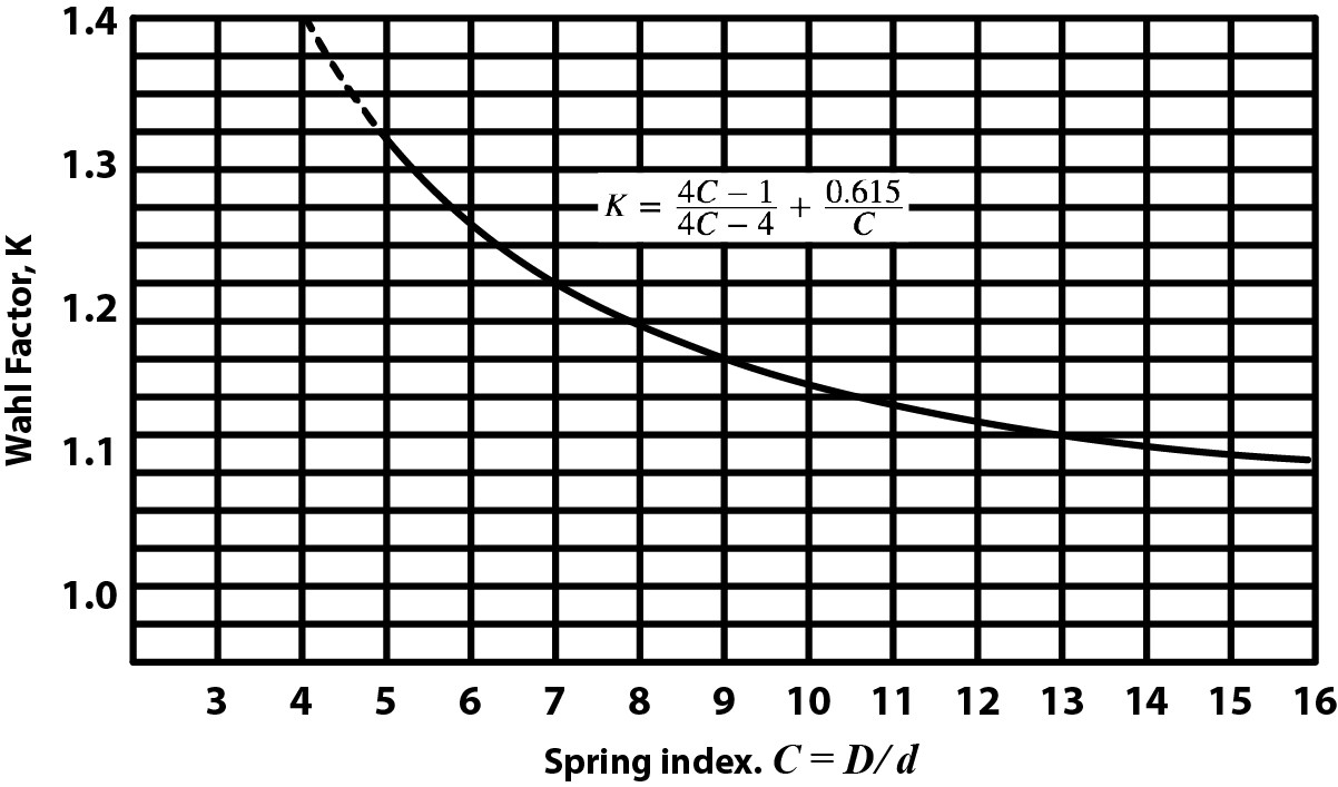
Other commonly used K value is given by:
$$ \large K = \frac{C+0.2}{C - 1} $$
Design of Helical Tension and Compression Springs (Cont.)
- Helical Springs are usually made of circular cross section wire or rod as shown in Figure 2. These springs are subjected to a torsional shear stress and to a transverse shear stress. There is also an additional stress effect due to the curvature of the helix.
 Figure 2. A typical helical compression spring arrangement.
- In order to take into account the effects of transverse shear and curvature, it is usual to multiply the torsional shear stress by a correction factor, called the Wahl Factor, K.
- The Shear Stress induced in a helical spring due to an axial load F is given by: $$ \large \tau = K \frac{8FD}{\pi d ^3} = K \frac{8FC}{\pi d ^2} $$
- (Cont.)
- (Cont.)
The Spring Rate for springs in parallel having individual spring rates as shown in Figure 4(a) below is:
Figure 4(a). Springs in parallel $ S = S _1 + S _2 + S _3 $
The Spring Rate for springs in series having individual spring rates as shown in Figure 4(b) below is:
Figure 4(b). Springs in series $$ S = \frac{1}{1/S_1 + 1/S_2 + 1/S_3} $$
Design of Helical Tension and Compression Springs (Cont.)
Figure 2. A typical helical compression spring arrangement.
- The Deflection of a helical spring due to an axial load F is given by: $$ \large \delta = \frac{8FD^3 n}{d ^4 G} = \frac{8FC^3 n}{d G} $$
where, n = number of active coils,
$ \delta $ = axial deflection (m),
G = modulus of rigidity (N/m2).
- The Spring Rate, or spring constant or stiffness is defined as the force per metre of deflection. $$ \large s = \frac{F}{\delta} (N/m) $$ Note: $ s = \large \frac{GD}{8C^3 n} $ for a helical spring under axial load.
- (Cont.)
- (Cont.) Figure 6: Length and Force Notations
- Buckling may occur in compression springs if the free length is over 4 x the spring mean diameter, unless the spring is properly guided.
The critical axial load that will cause buckling may be approximated by: $$ \large F _{cr} = sL _f K _L $$where, Fcr = axial load to produce buckling (N),
s = spring rate, N/m, of axial deflection (N),
Lf = free length of the spring (m),
KL = a factor depending on the ratio Lf /D - see table below.
Design of Helical Tension and Compression Springs (Cont.)
- Spring Ends for helical springs may be either plain, plain ground, squared, or squared and ground as shown in Figure 5 below.
 Figure 5: Common spring end conditions
Figure 6 (opposite) shows some examples of spring applications showing notations for lengths and forces.
 Note: The larger λ is, the steeper the coils
appear to be. Practically, λ < 120 to avoid
undesirable compression stresses in the wire.
Note: The larger λ is, the steeper the coils
appear to be. Practically, λ < 120 to avoid
undesirable compression stresses in the wire.
where, *p = pitch, n = number of active coils and d = wire diameterType of Ends Total Coils Solid Length Free Length Plain n (n + 1)d np + d Plain ground n nd np Squared n + 2 (n + 3)d np + 3d Squared & ground n + 2 (n + 2)d np + 2d
*Note: the pitch of a spring can be calculated from: $$ \Large P = \frac{L _f - L _s}{n} + d $$
Note: A further measure that can be taken to avoid buckling, is to ensure that the spring index C is as large as possible.Hinged Ends - Lf /D Hinged Ends - KL Built-in-Ends - Lf /D Built-in-Ends - KL 1 0.72 1 0.72 2 0.63 2 0.71 3 0.38 3 0.68 4 0.20 4 0.63 5 0.11 5 0.53 6 0.07 6 0.38 7 0.05 7 0.26 8 0.04 8 0.19
- (Cont.) Figure 6: Length and Force Notations
- (Cont.)
- Table 3 lists some common types of spring materials.
- Spring Drawing Conventions.
Figure 7 illustrates, by means of some examples, the conventional representations for helical coil springs. Note: in views and sections, take care to show the correct direction of the helix. Figure 7.
- ⬇ Design of Helical Tension Worked Example
Design of Helical Tension and Compression Springs (Cont.)
- Standard Wire Diameter The specification of the required spring wire diameter is one of the most important outcomes of the spring design. There are several types of materials typically used for spring wire, and wire is produced in sets of standard diameters covering quite a broad range.
Table 1 lists the most common standard wire gauges.
Table 2 lists the values for modulus of elasticity E and rigidity G for typical spring materials. Note again, that the wire diameter has a strong effect on the performance of the spring.
- Materials Used for Springs Virtually any elastic material can be used for a spring. However, most mechanical applications use metallic wire, either high-carbon steel, alloy steel, stainless steel, brass, bronze, or nickel-based alloys.
where, *p = pitch, n = number of active coils and d = wire diameterType of Ends Total Coils Solid Length Free Length Plain n (n + 1)d np + d Plain ground n nd np Squared n + 2 (n + 3)d np + 3d Squared & ground n + 2 (n + 2)d np + 2d
*Note: the pitch of a spring can be calculated from: $$ \Large P = \frac{L _f - L _s}{n} + d $$
Note: A further measure that can be taken to avoid buckling, is to ensure that the spring index C is as large as possible.Hinged Ends Built-in-Ends Lf /D KL Lf /D KL 1 0.72 1 0.72 2 0.63 2 0.71 3 0.38 3 0.68 4 0.20 4 0.63 5 0.11 5 0.53 6 0.07 6 0.38 7 0.05 7 0.26 8 0.04 8 0.19
- (Cont.)
-
Summary
⬇ Damped Free Vibration Summary
⬇ Design of Springs Summary -
Tutorials
- ⬇ Damped Free Vibration Tutorial
- ⬇ Design of Helical Tension Tutorial